


Hydrogen
Foto by nearshit17 on Pixabay
Production Storage and Transport Usage
For many years, hydrogen technologies have been an integral part of the process industry, especially in areas such as refineries, methanol, and ammonia production, where natural gas and coal primarily serve as the base materials for hydrogen production. With the increasing focus on a low-carbon future, the generation of hydrogen from renewable sources, for example through electrolysis using electricity from solar and wind energy, is gaining importance. This “green” hydrogen production is crucial for the desired decarbonization of the global economy and promises to play a key role in the energy supply of the future.
Throughout the hydrogen value chain – from generation through processing and distribution to storage – the equipment and materials used must meet extreme requirements. They are exposed to temperatures up to -253 °C, pressures up to 700 bar and beyond, as well as specific challenges such as hydrogen migration, which can cause material fatigue and cracking in metals. In addition, handling hydrogen requires special safety measures and materials that can withstand diffusion and the reactive properties of hydrogen. Therefore, the development and implementation of technologies for the safe and efficient handling of hydrogen are crucial for the successful integration of hydrogen as an energy carrier in a wide range of industrial applications.
- Hydrogen-induced embrittlement – Continuous exposure to hydrogen can lead to the phenomenon of hydrogen-induced embrittlement in certain materials. In this process, hydrogen penetrates the microstructure of materials, causing a reduction in mechanical strength and ultimately structural failure. To prevent such negative effects, the selection of materials that come into direct contact with hydrogen is of crucial importance. Typically, the use of austenitic steels such as 316L or 316Ti is recommended. In addition, specialized alloys such as Hastelloy C276, Inconel 718, or 2.4711 (Elgiloy®) offer high resistance against hydrogen embrittlement. Beyond material selection, it is important to follow specific guidelines and best practices in the design and maintenance of hydrogen applications to ensure the integrity and longevity of the components used.
- Hydrogen permeation – Hydrogen, the lightest element in the periodic table, consists of the second smallest atoms after helium. When in contact with metal surfaces, hydrogen molecules require only a small amount of energy to be split into individual atoms and eventually converted into protons (H+-ions). These protons can then penetrate metal and alloy structures, leading over time to changes in the signal of the measuring sensor. The degree of this effect increases with the energy introduced into the process by higher temperatures or pressures. To minimize the penetration of hydrogen through metal and thus a change in sensor signal, a gold coating provides an effective solution. Gold forms an efficient barrier against hydrogen permeation, with a significantly lower permeation rate compared to common industrial materials such as stainless steel 316L. This protective layer helps ensure the long-term stability and accuracy of sensors in hydrogen-rich environments by significantly reducing the interaction between hydrogen ions and the interior of the sensor. Thus, the reliability and lifespan of measuring instruments in demanding applications, especially at high temperatures and pressures, can be significantly improved.
- Leaks in hydrogen systems – Hydrogen can form explosive mixtures with air at concentrations as low as 4 mole percent in the air. Therefore, it is critical to avoid or greatly limit leaks in systems that work with hydrogen. An effective ventilation system is essential for the safe operation of hydrogen applications to minimize potential risks. For this reason, metallic seals are often chosen in hydrogen environments, as they offer higher tightness and resistance to the specific properties of hydrogen. Moreover, it is important that the leak rate within the measuring components is kept as low as possible to further increase safety and effectively prevent the unintended release of hydrogen. Modern measuring devices and systems are therefore designed to meet the specific requirements of hydrogen applications, including the use of materials and technologies that minimize leakage rates.
- Challenges in hydrogen storage – Storing hydrogen poses various challenges in measurement and handling depending on its state of aggregation. In gaseous form, hydrogen is stored at pressures up to 700 bar, requiring the use of pressure sensors that allow measurements up to 1,050 bar to accommodate temperature fluctuations and safety requirements. This is particularly important for use at hydrogen refueling stations. In its liquid form, hydrogen is kept at extremely low temperatures of -253 °C or below. Therefore, solutions for temperature monitoring must not only be capable of precisely measuring these extreme conditions but also not impair the effectiveness of tank insulation. Additionally, the materials and technologies used must be able to withstand harsh environmental conditions without losing accuracy or reliability. It is crucial that the measuring instruments are robust enough to ensure long-term stability and functionality under these extreme conditions, which is a key prerequisite for the safe and efficient use of hydrogen as an energy source.
➜ Hydrogen Production
Electrolysis
The production of green hydrogen, a key component of the energy transition, typically starts with the process of water electrolysis. In this technology, water molecules (H2O) are split into hydrogen (H2) and oxygen (O2) by the use of electricity derived from renewable sources such as solar energy, wind power, or hydropower.
Currently, three main types of electrolysis processes dominate the market:
- Alkaline electrolyzers use an aqueous solution of potassium hydroxide as the electrolyte to catalyze the splitting of water molecules.
- Proton exchange membrane electrolyzers (PEM) use a special polymer electrolyte membrane that allows for high efficiency in hydrogen production.
- “Solid Oxide Electrolyser Cell” technology (SOEC) relies on the electrochemical decomposition of steam into its components at high temperatures of up to 850 °C.
Each of these electrolysis techniques poses specific operational requirements, especially in terms of process pressure, temperature, and the medium used. To master these challenges, we offer a comprehensive range of measurement solutions for pressure, temperature, flow, and level. These instruments are crucial for the efficient and safe operation of the electrolyzers and thus contribute to the optimization of hydrogen production. In addition, they support the maintenance and monitoring of the facilities to ensure their longevity and reliability, which in turn contributes to cost efficiency and strengthens the green hydrogen economy.
- Low-wear design due to non-rotating spindle tip in the bonnet
- Low torque and smooth operation of valve handle even at high pressure
- Enhanced safety due to blow-out proof bonnet design
- Customer-specific combination of valves and instruments (hook-up) on request
- Standardised centre distances of 37 mm and 54 mm, suitable for WIKA differential pressure gauges and commonly used process transmitters
 Datasheet Datasheet |
| User Manual |
- Process- and procedure-specific solutions possible
- Operating limits: - Operating temperature: T = -80 ... +200 °C [-112 ... +392 °F] - Operating pressure: P = Vacuum to 25 bar [362,6 psi] - Limit density: ρ ≥400 kg/m3 [25,0 lbs/ft3]
- Wide variety of different electrical connections, process connections and materials
- Optionally with programmable and configurable head-mounted transmitter for 4 ... 20 mA field signals, HART®, PROFIBUS® PA and FOUNDATION™ Fieldbus
- Explosion-protected versions (option)
| Datasheet |
| User Manual |
| User Manual |
- Process- and procedure-specific production
- Operating limits: - Operating temperature: T = -196 ... +450 °C - Operating pressure: P = Vacuum up to 400 bar
- Wide variety of different process connections and materials
- Mounting of level sensors and guided wave radars possible as an option
| Datasheet |
| User Manual |
- High measurement accuracy
- Freely scalable measuring ranges
- Developed in accordance with the SIL 2 requirements
- Seven different case variants
- Configuration via DTM (Device Type Manager) in accordance with the FDT (Field Device Tool) concept (e.g. PACTware™)
 Datasheet Datasheet |
| User Manual |
| User Manual |
| User Manual |
- Measuring ranges from 0 ... 0.1 to 0 ... 6,000 bar [0 ... 3 to 0 ... 15,000 psi]
- Approved for use in hazardous areas, e.g. ATEX, IECEx, FM and CSA
| Datasheet |
| User Manual |
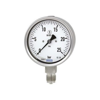
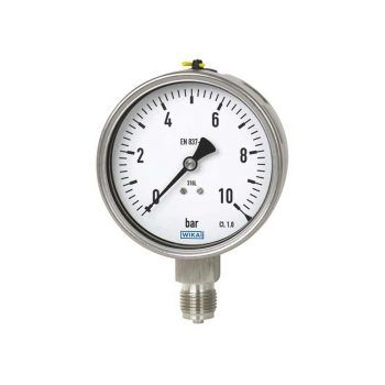
- Safety version with solid baffle wall designed in compliance with the requirements and test conditions of EN 837-1
- Excellent load-cycle stability and shock resistance
- Completely from stainless steel
- Scale ranges from 0 … 0.6 to 0 … 1,600 bar
|
Datasheet |
| User Manual |
| User Manual |
| User Manual |
| User Manual |
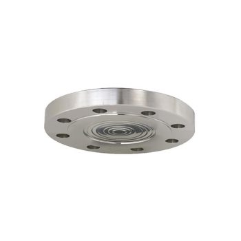
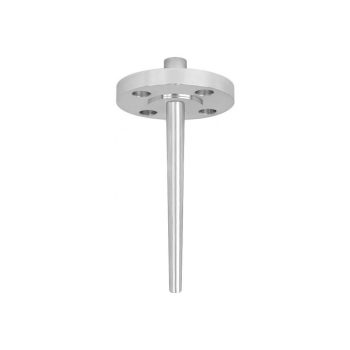
- Flange with flush welded diaphragm
- Common standards and nominal widths available
- Wide variety of different materials and material combinations
| Datasheet |
| User Manual |
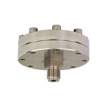
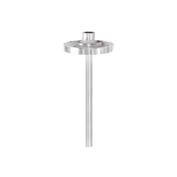
- Process connection with thread
- Version with internal diaphragm, large working volume, diaphragm seal parts screwed together
- Large selection of process connections and materials
- Flushing connections optionally available
| Datasheet |
| User Manual |
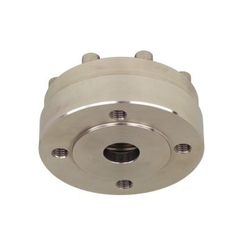
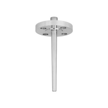
- Internal diaphragm with large working volume
- Special materials available
- Low temperature error due to large diaphragm diameter (realisation of low measuring ranges possible)
- Wide temperature application range due to large working volume
- Integrated flushing connections (optional)
| Datasheet |
| User Manual |
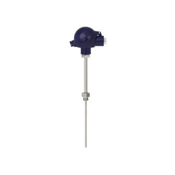
- Good price/performance ratio
- Wetted parts made of special material
- Non-wetted flange from 316/316L stainless steel
- Thermowell welded to one unit
- Possible thermowell forms: - tapered, straight or stepped - "Quill Tip" version (with open tip)
|
Datasheet (Model TW10-P)
|
|
Datasheet (Model TW10-F, Models TW10-P and TW10-R)
|
|
Datasheet (ScrutonWell® design)
|
|
User Manual
|
- Connection between flange and thermowell in threadwelded design
- Model TW10-S: No directly wetted welded joints (standard)
- Model TW10-B: Additional weld seam on the process side (sealing joint)
- Coating for corrosive or abrasive process loads
- Possible thermowell forms: - tapered, straight or stepped - “Quill Tip” version (with open tip)
|
Datasheet (Models TW10-S, TW10-B)
|
|
Datasheet (ScrutonWell® design)
|
|
User Manual
|
- Heavy-duty design
- Model TW10-F: Full penetration weld version Model TW10-P: With double fillet weld weld seam strength a = 3 mm Model TW10-R: With double fillet weld weld seam strength a = 6 mm
- Coating for corrosive or abrasive process loads
- Possible thermowell forms: - tapered, straight or stepped - “Quill Tip” version (with open tip)
- Welding process test to ASME Sec. IX
|
Datasheet (Model TW10-F, Models TW10-P and TW10-R)
|
|
Datasheet (ScrutonWell® design)
|
|
User Manual
|
- Sensor ranges from -196 ... +600 °C (-320 ... +1.112 °F)
- For mounting in all standard thermowell designs
- Spring-loaded measuring insert (replaceable)
- Pt100 or Pt1000 sensors
- Explosion-protected versions
| Datasheet |
| User Manual |
| User Manual |
| User Manual |
| User Manual |
| User Manual |
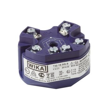
- TÜV zertifizierte SIL-Version für Schutzeinrichtungen entwickelt nach IEC 61508 (Option)
- Einsatz in Sicherheitsanwendungen bis SIL 2 (einzelnes Gerät) und SIL 3 (redundante Verschaltung)
- Konfigurierbar mit nahezu jedem offenen Soft- und Hardwaretool
- Universell für den Anschluss von 1 oder 2 Sensoren - Widerstandsthermometer, Widerstandssensor - Thermoelement, mV-Sensor - Potentiometer
- Signalisierung gemäß NAMUR NE43, Sensorbruchüberwachung gemäß NE89, EMV gemäß NE21

| Datenblatt |
| Bedienungsanleitung |
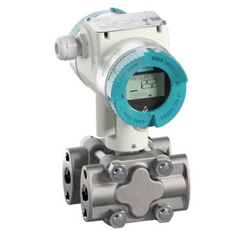
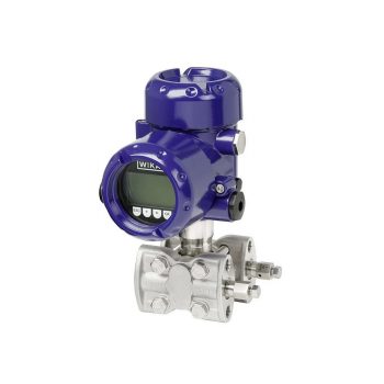
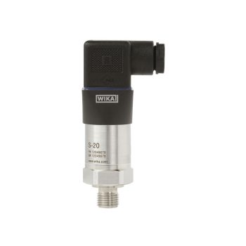
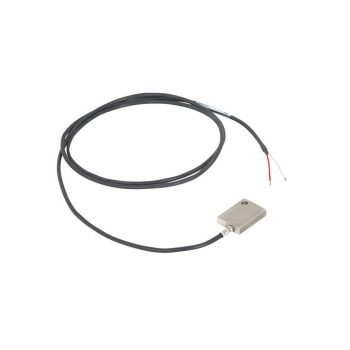
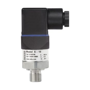
The digital pressure transmitter which features remote safety handling - developed according to IEC61508 standards for SIL2/3. Accuracy: 0,065 %
![]()
|
Datasheet
|
|
User Manual
|
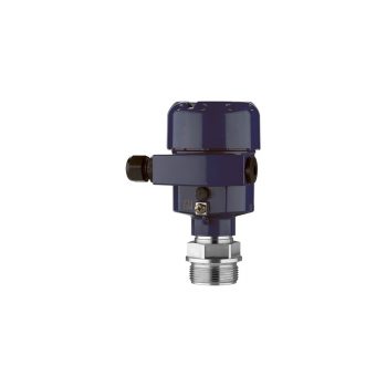
The digital "high performance" pressure transmitter which features remote safety handling and is ready for digitalization - developed according to IEC61508 standards for SIL2/3. Accuracy: 0,04 %
![]()
|
Datasheet
|
|
User Manual
|
Conventional H2 Production
The vast majority of hydrogen produced worldwide is still obtained through traditional, so-called “gray” technologies. These include processes such as:
- Steam Methane Reforming (SMR),
- Autothermal Reforming (ATR), and
- Partial Oxidation (POX) or gasification processes.
These processes, which occur at high temperatures of at least 750 °C and pressures above 40 bar, challenge the process equipment and measurement technology, as they are very energy-intensive.
In an effort to reduce their CO2 footprint and achieve so-called “blue” hydrogen production, facilities integrate additional process stages for CO2 capture and storage (CCS) as well as for CO2 utilization (CCU). These measures can bind CO2 for later use, preventing direct emissions into the atmosphere and thus contributing to a more environmentally friendly production.
To support these developments, robust and precise measurement technologies are required that can withstand the extreme conditions of hydrogen production while enabling efficient and safe monitoring of the processes. Advances in measurement technology, especially in pressure and temperature measurement as well as in gas analytics, play a crucial role in optimizing these processes and contribute to the realization of a more sustainable hydrogen economy.
- Low-wear design due to non-rotating spindle tip in the bonnet
- Low torque and smooth operation of valve handle even at high pressure
- Enhanced safety due to blow-out proof bonnet design
- Customer-specific combination of valves and instruments (hook-up) on request
- Standardised centre distances of 37 mm and 54 mm, suitable for WIKA differential pressure gauges and commonly used process transmitters
| Datasheet |
| User Manual |
- Process- and procedure-specific production
- Operating limits: - Operating temperature: T = -196 ... +450 °C - Operating pressure: P = Vacuum up to 400 bar
- Wide variety of different process connections and materials
- Mounting of level sensors and guided wave radars possible as an option
| Datasheet |
| User Manual |
- High measurement accuracy
- Freely scalable measuring ranges
- Developed in accordance with the SIL 2 requirements
- Seven different case variants
- Configuration via DTM (Device Type Manager) in accordance with the FDT (Field Device Tool) concept (e.g. PACTware™)
| Datasheet |
| User Manual |
| User Manual |
| User Manual |
- Measuring ranges from 0 ... 0.1 to 0 ... 6,000 bar [0 ... 3 to 0 ... 15,000 psi]
- Approved for use in hazardous areas, e.g. ATEX, IECEx, FM and CSA
| Datasheet |
| User Manual |
- Safety version with solid baffle wall designed in compliance with the requirements and test conditions of EN 837-1
- Excellent load-cycle stability and shock resistance
- Completely from stainless steel
- Scale ranges from 0 … 0.6 to 0 … 1,600 bar
|
Datasheet |
| User Manual |
| User Manual |
| User Manual |
| User Manual |
- Flange with flush welded diaphragm
- Common standards and nominal widths available
- Wide variety of different materials and material combinations
| Datasheet |
| User Manual |
- Sensor ranges from -196 ... +600 °C (-320 ... +1.112 °F)
- For mounting in all standard thermowell designs
- Spring-loaded measuring insert (replaceable)
- Pt100 or Pt1000 sensors
- Explosion-protected versions
| Datasheet |
| User Manual |
| User Manual |
| User Manual |
| User Manual |
| User Manual |
- TÜV zertifizierte SIL-Version für Schutzeinrichtungen entwickelt nach IEC 61508 (Option)
- Einsatz in Sicherheitsanwendungen bis SIL 2 (einzelnes Gerät) und SIL 3 (redundante Verschaltung)
- Konfigurierbar mit nahezu jedem offenen Soft- und Hardwaretool
- Universell für den Anschluss von 1 oder 2 Sensoren - Widerstandsthermometer, Widerstandssensor - Thermoelement, mV-Sensor - Potentiometer
- Signalisierung gemäß NAMUR NE43, Sensorbruchüberwachung gemäß NE89, EMV gemäß NE21
| Datenblatt |
| Bedienungsanleitung |

- Suitable for liquid, gas and steam flow measurement
- Accuracy ≤ ±0.5 % of actual flow rate
- Repeatability of measurement 0.1 %
- Lowest pressure loss in the family of primary flow elements
- Calibration may be performed if required
| Datasheet |
| User Manual |
- 3 times longer service life in comparison to purely ceramic protection tubes due to the monocrystalline structure of the sapphire sensor
- High process safety with processes up to 1,700 °C [3,092 °F] and 65 bar [943 psi]
- Reduction of unplanned downtime
- Increased safety through double sealing system against escape of toxic media
- Cost savings through the elimination of a purge system and the repairability of the sensor
| Datasheet |
| User Manual |
| User Manual |

- Versions to customer specification
- Various process connections
- Exchangeable measuring inserts
- Application in conjunction with a thermowell
- Explosion-protected versions Ex i, Ex n and NAMUR NE24
| Datasheet |
| User Manual |
| User Manual |
| User Manual |
- Process connection with thread
- Version with internal diaphragm, diaphragm seal parts screwed together
- Large selection of process connections and materials
- Flushing connections optionally available
| Datasheet |
| User Manual |
The digital pressure transmitter which features remote safety handling - developed according to IEC61508 standards for SIL2/3. Accuracy: 0,065 %
![]()
|
Datasheet
|
|
User Manual
|
The digital "high performance" pressure transmitter which features remote safety handling and is ready for digitalization - developed according to IEC61508 standards for SIL2/3. Accuracy: 0,04 %
![]()
|
Datasheet
|
|
User Manual
|
➜ Hydrogen Storage and Transport
Storage and Transport
If hydrogen is not produced directly at the point of use, its storage and distribution require special processes. Transport can be carried out via pipeline networks or, more commonly, in transport containers of various sizes and types. The pressure levels for storage vary significantly, from about 20 bar in liquid hydrogen tanks to extremely high pressures of 700 to 1,000 bar in high-pressure gas containers. In particular, liquefied hydrogen (LH2), stored at a temperature of -253 °C, is gaining importance due to its high energy density. This extremely low temperature leads to additional technical requirements and challenges.
Depending on whether the hydrogen is transported in gaseous form or as a cryogenic liquid, adapted measuring technologies are required. For gaseous hydrogen, robust pressure measuring devices are needed that can reliably monitor the high pressures. For handling cryogenic hydrogen, on the other hand, special cryogenic measuring instruments are required that can withstand both the extremely low temperatures and the pressure conditions. These measuring solutions must work precisely and reliably to ensure safe handling during transport and storage, taking into account the specific physical properties of hydrogen.
- Low-wear design due to non-rotating spindle tip in the bonnet
- Low torque and smooth operation of valve handle even at high pressure
- Enhanced safety due to blow-out proof bonnet design
- Customer-specific combination of valves and instruments (hook-up) on request
- Standardised centre distances of 37 mm and 54 mm, suitable for WIKA differential pressure gauges and commonly used process transmitters
| Datasheet |
| User Manual |
- Measuring ranges from 0 ... 0.1 to 0 ... 6,000 bar [0 ... 3 to 0 ... 15,000 psi]
- Approved for use in hazardous areas, e.g. ATEX, IECEx, FM and CSA
| Datasheet |
| User Manual |
- Sensor ranges from -196 ... +600 °C (-320 ... +1.112 °F)
- For mounting in all standard thermowell designs
- Spring-loaded measuring insert (replaceable)
- Pt100 or Pt1000 sensors
- Explosion-protected versions
| Datasheet |
| User Manual |
| User Manual |
| User Manual |
| User Manual |
| User Manual |
- TÜV zertifizierte SIL-Version für Schutzeinrichtungen entwickelt nach IEC 61508 (Option)
- Einsatz in Sicherheitsanwendungen bis SIL 2 (einzelnes Gerät) und SIL 3 (redundante Verschaltung)
- Konfigurierbar mit nahezu jedem offenen Soft- und Hardwaretool
- Universell für den Anschluss von 1 oder 2 Sensoren - Widerstandsthermometer, Widerstandssensor - Thermoelement, mV-Sensor - Potentiometer
- Signalisierung gemäß NAMUR NE43, Sensorbruchüberwachung gemäß NE89, EMV gemäß NE21
| Datenblatt |
| Bedienungsanleitung |
- Excellent load-cycle stability and shock resistance
- All stainless steel construction
- German Lloyd approva
- Scale ranges up to 0 … 1,600 bar
| Datasheet |
| User Manual |
| User Manual |
| User Manual |
| User Manual |
- High measurement accuracy
- Freely scalable measuring ranges
- Developed in accordance with the SIL 2 requirements
- Seven different case variants
- Configuration via DTM (Device Type Manager) in accordance with the FDT (Field Device Tool) concept (e.g. PACTware™)
| Datasheet |
| User Manual |
| User Manual |
| User Manual |
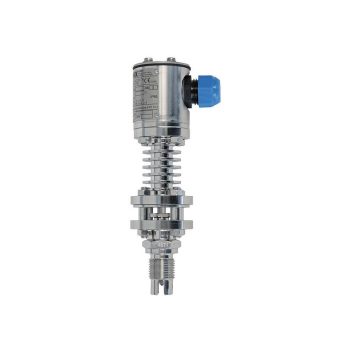
- For extreme operating conditions
- Compact and robust design
- Diagnostic function (option)
- Signal clamping (option)
- Customer-specific modifications possible
| Datasheet |
| User Manual |
- High-quality machining guarantees smooth operation with low torque and low wear
- Leak-tested tightness in accordance with BS6755 / ISO 5208 leakage rate A
- Large selection of materials and configurations available
- Customer-specific combination of valves and instruments (hook-up) on request
| Datasheet |
- One-piece design
- Laser marked for identification
- Large selection of materials and configurations available
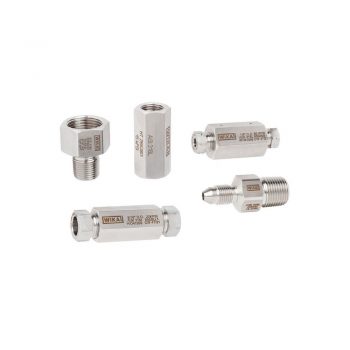
- Customer-specific combination of adapters, fittings, valves and measuring instruments (instrument hook-up) on request
| Datasheet |
- Temperature ranges from -269 … +400 °C
- Versions for pressure ranges from vacuum to 500 bar
- Special versions: High pressure, interface measurement
- Signal processing is made using a separate model OSA-S switching amplifier
| Datasheet |
| Datasheet |
| User Manual |
- Media compatibility: Oil, diesel, refrigerants and other liquids
- Level: Up to 4 switching outputs, freely definable as normally open, normally closed or change-over contact
- Level and temperature: Up to 3 switching outputs, freely definable as normally open, normally closed or change-over contact and 1 bimetal temperature switch or Pt100/Pt1000, accuracy: Class B
- Potential-free switching reed contacts
| Datasheet |
- Good price/performance ratio
- Wetted parts made of special material
- Non-wetted flange from 316/316L stainless steel
- Thermowell welded to one unit
- Possible thermowell forms: - tapered, straight or stepped - "Quill Tip" version (with open tip)
|
Datasheet (Model TW10-P)
|
|
Datasheet (Model TW10-F, Models TW10-P and TW10-R)
|
|
Datasheet (ScrutonWell® design)
|
|
User Manual
|
- Connection between flange and thermowell in threadwelded design
- Model TW10-S: No directly wetted welded joints (standard)
- Model TW10-B: Additional weld seam on the process side (sealing joint)
- Coating for corrosive or abrasive process loads
- Possible thermowell forms: - tapered, straight or stepped - “Quill Tip” version (with open tip)
|
Datasheet (Models TW10-S, TW10-B)
|
|
Datasheet (ScrutonWell® design)
|
|
User Manual
|
- Heavy-duty design
- Model TW10-F: Full penetration weld version Model TW10-P: With double fillet weld weld seam strength a = 3 mm Model TW10-R: With double fillet weld weld seam strength a = 6 mm
- Coating for corrosive or abrasive process loads
- Possible thermowell forms: - tapered, straight or stepped - “Quill Tip” version (with open tip)
- Welding process test to ASME Sec. IX
|
Datasheet (Model TW10-F, Models TW10-P and TW10-R)
|
|
Datasheet (ScrutonWell® design)
|
|
User Manual
|
- Case aluminium, epoxy resin coated
- Ingress protection IP 65, NEMA 4
- Ambient temperature -40 ... +85 °C
- 1 switch point, SPDT or DPDT with a high contact rating of up to 15 A/AC 220 V
- Capillary up to 10 m
![]()
![]()
|
Datasheet
|
|
User Manual
|
The digital pressure transmitter which features remote safety handling - developed according to IEC61508 standards for SIL2/3. Accuracy: 0,065 %
![]()
|
Datasheet
|
|
User Manual
|
The digital "high performance" pressure transmitter which features remote safety handling and is ready for digitalization - developed according to IEC61508 standards for SIL2/3. Accuracy: 0,04 %
![]()
|
Datasheet
|
|
User Manual
|
Compression
Compression technologies are central to the efficiency of hydrogen infrastructure and utilization. Compressors are indispensable for hydrogen vehicle refueling stations as they compress the gas to the necessary high-pressure levels to ensure optimal energy density in the vehicle tanks. Membrane compressors, in particular, are used because they prevent contamination of the hydrogen with oil, which is essential for the fuel’s purity.
In addition to pure compression, precise monitoring and control of operating parameters are crucial for the safety and efficiency of the process. Temperature, pressure, and level measurements are critical at various points in the compressor. Continuous measurement methods and switching systems are also used to ensure smooth and safe operation.
Monitoring the pressure progression not only allows for optimization of the compressor’s performance but also for early detection of maintenance needs and minimization of downtime. In addition, temperature monitoring systems protect against overheating, while level sensors provide continuous monitoring of the medium to enable efficient and safe compression. The integration of advanced sensors and intelligent monitoring technologies thus increases the efficiency, safety, and reliability in the operation of hydrogen compressors.
- Measuring ranges from 0 ... 0.1 to 0 ... 6,000 bar [0 ... 3 to 0 ... 15,000 psi]
- Approved for use in hazardous areas, e.g. ATEX, IECEx, FM and CSA
| Datasheet |
| User Manual |
- Sensor ranges from -196 ... +600 °C (-320 ... +1.112 °F)
- For mounting in all standard thermowell designs
- Spring-loaded measuring insert (replaceable)
- Pt100 or Pt1000 sensors
- Explosion-protected versions
| Datasheet |
| User Manual |
| User Manual |
| User Manual |
| User Manual |
| User Manual |
- TÜV zertifizierte SIL-Version für Schutzeinrichtungen entwickelt nach IEC 61508 (Option)
- Einsatz in Sicherheitsanwendungen bis SIL 2 (einzelnes Gerät) und SIL 3 (redundante Verschaltung)
- Konfigurierbar mit nahezu jedem offenen Soft- und Hardwaretool
- Universell für den Anschluss von 1 oder 2 Sensoren - Widerstandsthermometer, Widerstandssensor - Thermoelement, mV-Sensor - Potentiometer
- Signalisierung gemäß NAMUR NE43, Sensorbruchüberwachung gemäß NE89, EMV gemäß NE21
| Datenblatt |
| Bedienungsanleitung |
- Excellent load-cycle stability and shock resistance
- All stainless steel construction
- German Lloyd approva
- Scale ranges up to 0 … 1,600 bar
| Datasheet |
| User Manual |
| User Manual |
| User Manual |
| User Manual |
- Media compatibility: Oil, diesel, refrigerants and other liquids
- Level: Up to 4 switching outputs, freely definable as normally open, normally closed or change-over contact
- Level and temperature: Up to 3 switching outputs, freely definable as normally open, normally closed or change-over contact and 1 bimetal temperature switch or Pt100/Pt1000, accuracy: Class B
- Potential-free switching reed contacts
| Datasheet |
- Good price/performance ratio
- Wetted parts made of special material
- Non-wetted flange from 316/316L stainless steel
- Thermowell welded to one unit
- Possible thermowell forms: - tapered, straight or stepped - "Quill Tip" version (with open tip)
|
Datasheet (Model TW10-P)
|
|
Datasheet (Model TW10-F, Models TW10-P and TW10-R)
|
|
Datasheet (ScrutonWell® design)
|
|
User Manual
|
- Connection between flange and thermowell in threadwelded design
- Model TW10-S: No directly wetted welded joints (standard)
- Model TW10-B: Additional weld seam on the process side (sealing joint)
- Coating for corrosive or abrasive process loads
- Possible thermowell forms: - tapered, straight or stepped - “Quill Tip” version (with open tip)
|
Datasheet (Models TW10-S, TW10-B)
|
|
Datasheet (ScrutonWell® design)
|
|
User Manual
|
- Heavy-duty design
- Model TW10-F: Full penetration weld version Model TW10-P: With double fillet weld weld seam strength a = 3 mm Model TW10-R: With double fillet weld weld seam strength a = 6 mm
- Coating for corrosive or abrasive process loads
- Possible thermowell forms: - tapered, straight or stepped - “Quill Tip” version (with open tip)
- Welding process test to ASME Sec. IX
|
Datasheet (Model TW10-F, Models TW10-P and TW10-R)
|
|
Datasheet (ScrutonWell® design)
|
|
User Manual
|
- Case aluminium, epoxy resin coated
- Ingress protection IP 65, NEMA 4
- Ambient temperature -40 ... +85 °C
- 1 switch point, SPDT or DPDT with a high contact rating of up to 15 A/AC 220 V
- Capillary up to 10 m
![]()
![]()
|
Datasheet
|
|
User Manual
|
- Application at medium temperatures up to +135 °C
- Mounting position as required
- Accuracy ±2 mm
- Explosion-protected version Ex i
| Datasheet |
- Safety version with solid baffle wall designed in compliance with the requirements and test conditions of EN 837-1
- Excellent load-cycle stability and shock resistance
- Completely from stainless steel
- Scale ranges from 0 … 0.6 to 0 … 1,600 bar
|
Datasheet |
| User Manual |
| User Manual |
| User Manual |
| User Manual |
The digital pressure transmitter which features remote safety handling - developed according to IEC61508 standards for SIL2/3. Accuracy: 0,065 %
![]()
|
Datasheet
|
|
User Manual
|
The digital "high performance" pressure transmitter which features remote safety handling and is ready for digitalization - developed according to IEC61508 standards for SIL2/3. Accuracy: 0,04 %
![]()
|
Datasheet
|
|
User Manual
|
Hydrogen Fuel Stations
Hydrogen fuel stations are essential for the promotion of hydrogen mobility. They enable the refueling of vehicles with hydrogen as a fuel and typically consist of various components:
- A hydrogen supply that includes a low-pressure storage, usually up to 250 bar. The stored hydrogen can be in either gaseous or liquid state.
- A compression area, where the hydrogen is compressed into medium and high-pressure storage up to 900 bar, to achieve the required density for vehicle fuel supply.
- A cooling unit is required, as the hydrogen must be cooled to temperatures of about -40 °C before it can be safely filled into the vehicle tank, to ensure optimal density and maximize the efficiency of the refueling process.
- A dispensing pump, specifically designed for the high-pressure refueling process of hydrogen, enabling fast and safe refueling.
During the refueling process, careful monitoring of temperature and pressure at various points of the system is essential to ensure safety and efficiency. Furthermore, all components and processes must meet the strict requirements of explosion protection to minimize risks in handling the highly flammable hydrogen gas. Therefore, the implementation of reliable monitoring systems and safety measures is crucial to create and maintain a safe infrastructure for hydrogen mobility.
- Measuring ranges from 0 ... 0.1 to 0 ... 6,000 bar [0 ... 3 to 0 ... 15,000 psi]
- Approved for use in hazardous areas, e.g. ATEX, IECEx, FM and CSA
| Datasheet |
| User Manual |
- Sensor ranges from -196 ... +600 °C (-320 ... +1.112 °F)
- For mounting in all standard thermowell designs
- Spring-loaded measuring insert (replaceable)
- Pt100 or Pt1000 sensors
- Explosion-protected versions
| Datasheet |
| User Manual |
| User Manual |
| User Manual |
| User Manual |
| User Manual |
- TÜV zertifizierte SIL-Version für Schutzeinrichtungen entwickelt nach IEC 61508 (Option)
- Einsatz in Sicherheitsanwendungen bis SIL 2 (einzelnes Gerät) und SIL 3 (redundante Verschaltung)
- Konfigurierbar mit nahezu jedem offenen Soft- und Hardwaretool
- Universell für den Anschluss von 1 oder 2 Sensoren - Widerstandsthermometer, Widerstandssensor - Thermoelement, mV-Sensor - Potentiometer
- Signalisierung gemäß NAMUR NE43, Sensorbruchüberwachung gemäß NE89, EMV gemäß NE21
| Datenblatt |
| Bedienungsanleitung |
- Excellent load-cycle stability and shock resistance
- All stainless steel construction
- German Lloyd approva
- Scale ranges up to 0 … 1,600 bar
| Datasheet |
| User Manual |
| User Manual |
| User Manual |
| User Manual |
- Good price/performance ratio
- Wetted parts made of special material
- Non-wetted flange from 316/316L stainless steel
- Thermowell welded to one unit
- Possible thermowell forms: - tapered, straight or stepped - "Quill Tip" version (with open tip)
|
Datasheet (Model TW10-P)
|
|
Datasheet (Model TW10-F, Models TW10-P and TW10-R)
|
|
Datasheet (ScrutonWell® design)
|
|
User Manual
|
- Connection between flange and thermowell in threadwelded design
- Model TW10-S: No directly wetted welded joints (standard)
- Model TW10-B: Additional weld seam on the process side (sealing joint)
- Coating for corrosive or abrasive process loads
- Possible thermowell forms: - tapered, straight or stepped - “Quill Tip” version (with open tip)
|
Datasheet (Models TW10-S, TW10-B)
|
|
Datasheet (ScrutonWell® design)
|
|
User Manual
|
- Heavy-duty design
- Model TW10-F: Full penetration weld version Model TW10-P: With double fillet weld weld seam strength a = 3 mm Model TW10-R: With double fillet weld weld seam strength a = 6 mm
- Coating for corrosive or abrasive process loads
- Possible thermowell forms: - tapered, straight or stepped - “Quill Tip” version (with open tip)
- Welding process test to ASME Sec. IX
|
Datasheet (Model TW10-F, Models TW10-P and TW10-R)
|
|
Datasheet (ScrutonWell® design)
|
|
User Manual
|
- Safety version with solid baffle wall designed in compliance with the requirements and test conditions of EN 837-1
- Excellent load-cycle stability and shock resistance
- Completely from stainless steel
- Scale ranges from 0 … 0.6 to 0 … 1,600 bar
|
Datasheet |
| User Manual |
| User Manual |
| User Manual |
| User Manual |
- Low-wear design due to non-rotating spindle tip in the bonnet
- Low torque and smooth operation of valve handle even at high pressure
- Enhanced safety due to blow-out proof bonnet design
- Customer-specific combination of valves and instruments (hook-up) on request
- Standardised centre distances of 37 mm and 54 mm, suitable for WIKA differential pressure gauges and commonly used process transmitters
| Datasheet |
| User Manual |
- Versions to customer specification
- Various process connections
- Short response times
- Robust, vibration-resistant design
- Various thermocouple types and electrical connection types
| Datasheet |
| Datasheet |
| User Manual |
| User Manual |
| User Manual |
![]()
|
Datasheet
|
|
User Manual
|
|
User Manual
|
|
User Manual
|
|
User Manual
|
The digital pressure transmitter which features remote safety handling - developed according to IEC61508 standards for SIL2/3. Accuracy: 0,065 %
![]()
|
Datasheet
|
|
User Manual
|
The digital "high performance" pressure transmitter which features remote safety handling and is ready for digitalization - developed according to IEC61508 standards for SIL2/3. Accuracy: 0,04 %
![]()
|
Datasheet
|
|
User Manual
|
➜ Use of Hydrogen
Stationary Fuel Cells
The use of complex stationary fuel cell systems for a variety of applications is steadily growing. These systems are increasingly serving as emergency power supplies, as an alternative to conventional diesel generators, and are being used in the energy supply of public facilities and private homes. Particularly interesting are these systems in combination with renewable energy sources such as solar and wind power, which serve as local suppliers of green energy. The excess hydrogen produced can be compressed and stored for later use, ensuring an efficient and sustainable energy supply.
Similar to electrolyzers that split water into hydrogen and oxygen, not all sensors and measuring devices in these systems come into direct contact with hydrogen. It is essential to also carefully monitor and regulate supporting systems such as water circuits or air circulation to guarantee the optimal performance and safety of the fuel cells. This monitoring involves measuring temperature, pressure, and flow in various parts of the system to ensure efficient and trouble-free operation and to ensure the longevity of the components.
- Measuring ranges from 0 ... 0.1 to 0 ... 6,000 bar [0 ... 3 to 0 ... 15,000 psi]
- Approved for use in hazardous areas, e.g. ATEX, IECEx, FM and CSA
| Datasheet |
| User Manual |
![]()
|
Datasheet
|
|
User Manual
|
|
User Manual
|
|
User Manual
|
|
User Manual
|
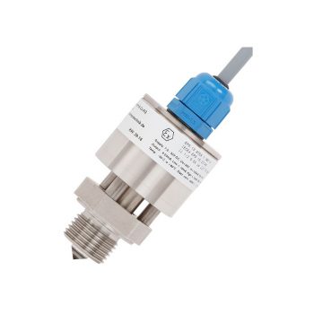
- Measuring ranges from 0 … 0.05 to 0 … 1,000 bar
- Non-linearity 0.25 % or 0.5 %
- Output 4 ... 20 mA, DC 0 ... 10 V, DC 0 ... 5 V and others
- Electrical connection: Angular connector form A and C, circular connector M12 x 1, cable outlet 2 m
- Process connection G ¼ A DIN 3852-E, ¼ NPT and others
|
Datasheet |
| User Manual |
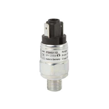
- Setting ranges: 0.2 … 2 bar [3 ... 30 psi] to 30 ... 320 bar [450 ... 4,600 psi] and -0.85 ... -0.15 bar [-25 inHg ... -5 inHg]
- Non-repeatability of the switch point: ≤ 2 % of span
- Switching functions: Normally closed, normally open or change-over contact
- Media: Compressed air, neutral and self-lubricating fluids and neutral gases
| Datasheet |
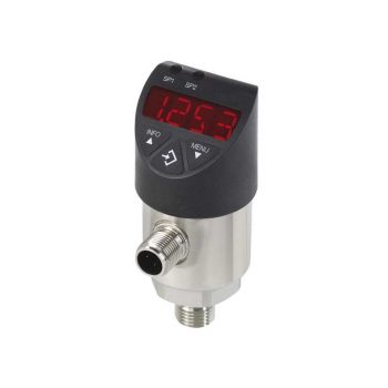
- Easily readable, robust digital display
- Intuitive and fast setup
- Easy and flexible mounting configurations
- Flexibly configurable and scalable output signals
| Datasheet |
| User Manual |
- Application at medium temperatures up to +135 °C
- Mounting position as required
- Accuracy ±2 mm
- Explosion-protected version Ex i
| Datasheet |
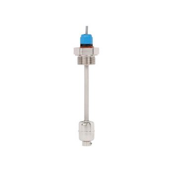
- Maximum reliability thanks to high-quality reed contacts
- Very high variety and customer-specific solutions possible
- Simple and fast installation
| Datasheet |
| User Manual |
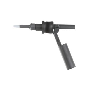
- From customisation to design-in solution
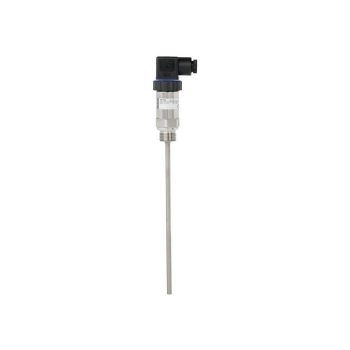
- Low variance by local adjustment of the normally open/normally closed switching function via rotation of the float
- Various materials and up to 109 switching cycles guarantee a long service life
| Datasheet |
| User Manual |
- Media compatibility: Oil, water, diesel, refrigerants and other liquids
- Permissible medium temperature range: -30 ... +120 °C [-22 ... +248 °F]
- Output signal: Resistance in a 3-wire potentiometer circuit, current output 4 ... 20 mA
- Measuring principle: Reed-chain technology
- Accuracy, resolution: 24 mm [0.9 in], 12 mm [0.5 in], 10 mm [0.4 in], 6 mm [0.2 in] oder 3 mm [0.1 in]
| Datasheet |
| User Manual |
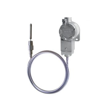
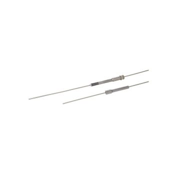
- Sensor ranges from -40 ... +1,200 °C [-40 ... +2,192 °F]
- Made of mineral-insulated sheathed measuring cable
- Functional safety (SIL) with model T32 temperature transmitter
- Spring-loaded design
- Explosion-protected versions are available for many approval types (see data sheet page 2)
![]()
|
Datasheet
|
|
User Manual
|
|
User Manual
|
|
User Manual
|
- Sensor ranges from -196 ... +600 °C [-320 ... +1.112 °F]
- Made of mineral-insulated sheathed cable
- Functional safety (SIL) with model T32 temperature transmitter
- Spring-loaded design
- Explosion-protected versions are available for many approval types (see data sheet page 2)
![]()
|
Datasheet
|
|
User Manual
|
|
User Manual
|
|
User Manual
|
|
User Manual
|
|
Datasheet |
| User Manual |
|
Datasheet
|
|
User Manual
|
The digital pressure transmitter which features remote safety handling - developed according to IEC61508 standards for SIL2/3. Accuracy: 0,065 %
![]()
|
Datasheet
|
|
User Manual
|
The digital "high performance" pressure transmitter which features remote safety handling and is ready for digitalization - developed according to IEC61508 standards for SIL2/3. Accuracy: 0,04 %
![]()
|
Datasheet
|
|
User Manual
|
Mobile Fuel Cells
On the path to a more environmentally friendly mobility with reduced CO2 emissions, hydrogen is increasingly seen as a promising alternative, especially in the field of commercial vehicles. This includes trucks, buses, vehicles for municipal services, forklifts, and trains. The refueling of these vehicles typically occurs at a pressure of 350 bar, with a trend towards a standard of 700 bar, which is already being used in passenger cars. This development reflects the efforts to achieve a higher energy density in the tank in order to extend the range of the vehicles and shorten refueling times, which is crucial for wider acceptance and use of hydrogen as fuel.
- For extreme operating conditions
- Compact and robust design
- Diagnostic function (option)
- Signal clamping (option)
- Customer-specific modifications possible
| Datasheet |
| User Manual |
- Safety version with solid baffle wall designed in compliance with the requirements and test conditions of EN 837-1
- Excellent load-cycle stability and shock resistance
- Completely from stainless steel
- Scale ranges from 0 … 0.6 to 0 … 1,600 bar
|
Datasheet |
| User Manual |
| User Manual |
| User Manual |
| User Manual |
The digital pressure transmitter which features remote safety handling - developed according to IEC61508 standards for SIL2/3. Accuracy: 0,065 %
![]()
|
Datasheet
|
|
User Manual
|
The digital "high performance" pressure transmitter which features remote safety handling and is ready for digitalization - developed according to IEC61508 standards for SIL2/3. Accuracy: 0,04 %
![]()
|
Datasheet
|
|
User Manual
|