


Iron and Steel
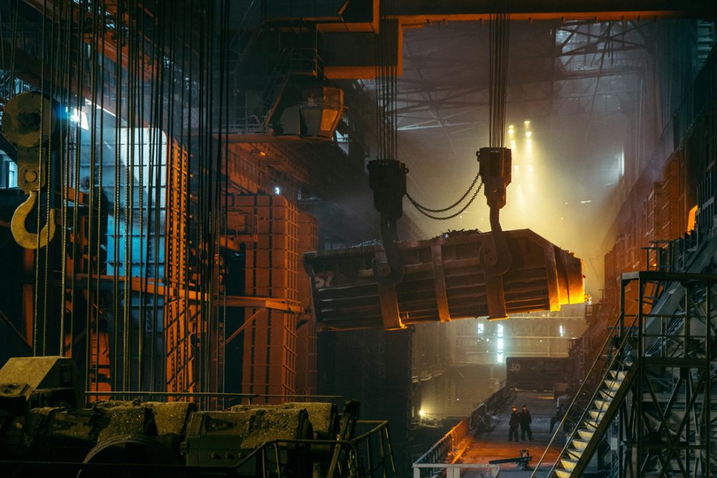
Foto by Ant Rozetsky on Unsplash
Sinter Plant Coking Plant Pellet plant Blast Furnace Direct reduction plant Oxygen steel converter Electric Arc Furnace Pan oven Continuous casting plant
Steel is a fundamental building material in a variety of industries, from construction to mechanical engineering to precision mechanics. Given the demanding process conditions and high demand for raw materials and energy, the industry places great emphasis on increasing the efficiency of its manufacturing processes. The quality of products and the consistency of production runs are crucial to minimize process costs. Iron and steel production requires highly resistant measuring and testing technology capable of identifying deviations precisely, reliably, and cost-effectively.
To ensure product quality and production efficiency, the use of advanced sensor technology is essential. This includes temperature, pressure, and humidity measuring devices capable of withstanding extreme conditions. In addition, material testing is necessary to determine the mechanical properties and chemical composition of the steel. Technologies such as spectroscopy and non-destructive testing (NDT) play an important role in this regard.
Continuous monitoring of production processes not only ensures compliance with quality standards but also enables early detection of problems that could lead to failures or inefficient resource use. Modern control systems and automation techniques help optimize material flow and improve energy efficiency.
To meet the growing demands for sustainability and energy efficiency, manufacturers are increasingly integrating technologies for energy and material recovery into their processes. By using waste heat for power generation or returning process gases to the production cycle, significant efficiency improvements and cost reductions can be achieved.
Therefore, the development and implementation of robust and reliable measuring and testing technologies are key elements in making the future of the iron and steel industry sustainable and competitive.
Sintering Plant
During sintering, fine ores, coke, recycled materials from the smelting process, and various additives are prepared by partial melting to optimize them for use in the blast furnace. This process improves gas permeability and facilitates the reduction of ores by the gases in the blast furnace.
Precise control of the sintering plant, especially the sinter hood and its associated burner unit, is crucial for the sintering process. Uniform and controlled temperature distribution in the furnace is essential to ensure a continuous process flow and to guarantee the high quality of the sintered product. Furnace failure would interrupt the entire process, while temperature fluctuations could adversely affect the quality of the sinter.
In addition, monitoring the exhaust gas composition plays an important role in meeting environmental regulations and optimizing the efficiency of the combustion process. Modern sintering plants utilize advanced measurement technology to monitor temperature, pressure, and gas composition. This includes thermocouples for temperature measurement, pressure sensors for monitoring gas flow, and analyzers for determining gas composition. Efficient filtration systems for dust reduction and exhaust gas cleaning systems also contribute to environmental protection.
Continuous improvement of measurement and control technology, including the implementation of automation and control systems, increases process efficiency and contributes to the reduction of energy consumption and emissions. Thus, the sintering process makes an important contribution to sustainability in steel production.
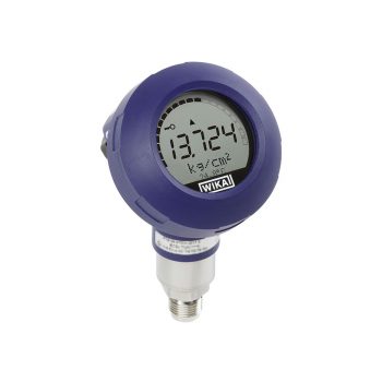
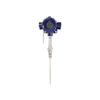
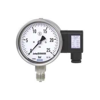
- Multi-functional display
- Simple menu navigation
- Conductive plastic case
- Large LC display, rotatable
- Approvals for hazardous areas
 Datasheet Datasheet |
| User Manual |
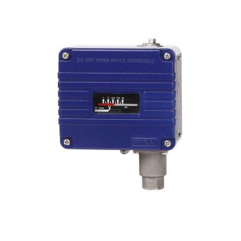
- Switch differential adjustable within a wide range of up to 60 % of the setting range to realise flexible on/off controls
- Robust aluminium case
- Switch point repeatability of ≤ 0.5 % for reliable switching
- High-quality micro switches with long service life
- Up to 2 possible positions for electrical connection
| Datasheet |
| User Manual |
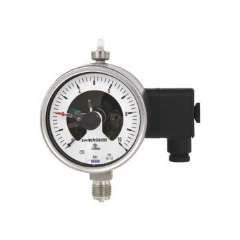
- Up to 4 switch contacts per instrument
- Also available with case filling for high dynamic pressure loads or vibrations
- Instruments with inductive contacts for use in hazardous areas
- Instruments with contacts for PLC applications
- Instruments optionally available in safety version S3 per EN 837
| Datasheet |
| User Manual |
| User Manual |
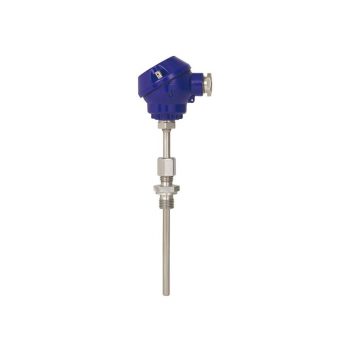
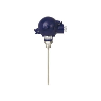
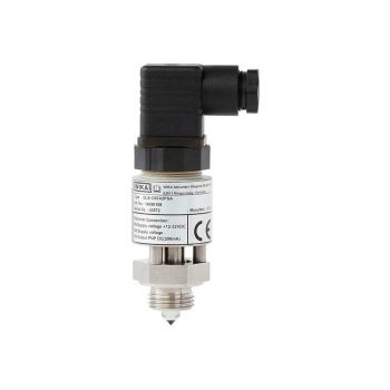
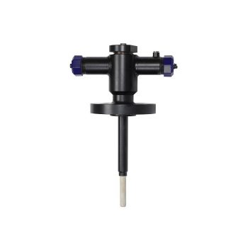
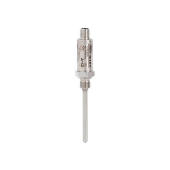
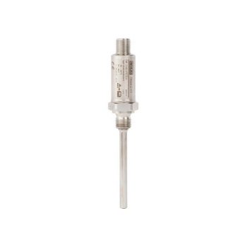
- Sensor ranges from -196 ... +500 °C [-320 ... +932 °F]
- Compact design
- Universal application
- Direct installation into the process
- Explosion-protected versions are available for many approval types (see data sheet page 2)
| Datasheet |
| User Manual |
| User Manual |
| User Manual |
| User Manual |
| User Manual |
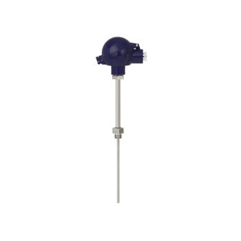
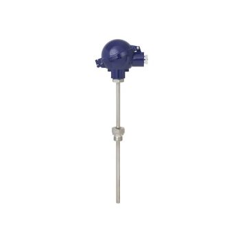
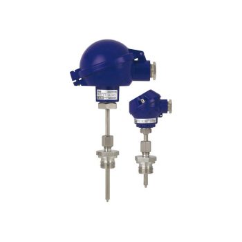
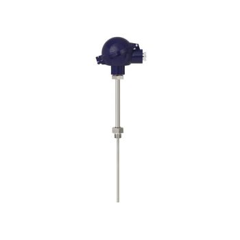
- Sensor ranges from -196 ... +600 °C (-320 ... +1.112 °F)
- For mounting in all standard thermowell designs
- Spring-loaded measuring insert (replaceable)
- Pt100 or Pt1000 sensors
- Explosion-protected versions
| Datasheet |
| User Manual |
| User Manual |
| User Manual |
| User Manual |
| User Manual |
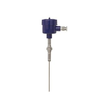
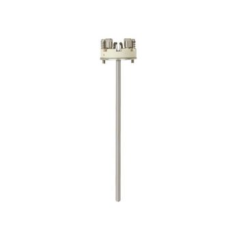
- Sensor ranges from -196 ... +600 °C [-320 ... +1,112 °F]
- Measuring insert replaceable
- For many thermowell designs
- Explosion-protected versions are available for many approval types (see data sheet page 2)
![]()
|
Datasheet
|
|
User Manual
|
|
User Manual
|
|
User Manual
|
|
User Manual
|
|
User Manual
|
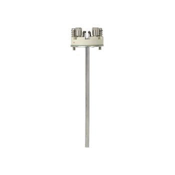
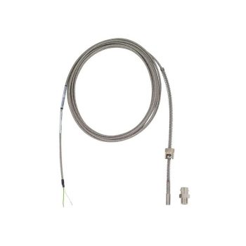
- Sensor ranges from -196 ... +600 °C [-320 ... +1,112 °F]
- Made of mineral-insulated sheathed measuring cable
- For all standard thermowell designs
- Spring-loaded design
- Explosion-protected versions are available for many approval types (see data sheet page 2)
![]()
|
Datasheet
|
|
User Manual
|
|
User Manual
|
|
User Manual
|
|
User Manual
|
|
User Manual
|
- Sensor ranges from -196 ... +600 °C [-320 ... +1,112 °F]
- With integrated perforated protection tube model TW35
- Explosion-protected versions are available for many approval types (see data sheet page 2)
![]()
|
Datasheet
|
|
User Manual
|
|
User Manual
|
|
User Manual
|
|
User Manual
|
|
User Manual
|
- Sensor ranges from -196 ... +600 °C [-320 ... +1,112 °F]
- For insertion, screw-in with optional process connection
- Connection head form B or JS
- Explosion-protected versions are available for many approval types (see data sheet page 2)
![]()
|
Datasheet
|
|
User Manual
|
|
User Manual
|
|
User Manual
|
|
User Manual
|
|
User Manual
|
- Sensor ranges from -196 ... +600 °C [-320 ... +1,112 °F]
- With integrated fabricated protection tube
- Spring-loaded measuring insert (replaceable)
- Explosion-protected versions are available for many approval types (see data sheet page 2)
![]()
|
Datasheet
|
|
Bedienungsanleitung
|
|
Bedienungsanleitung
|
|
Bedienungsanleitung
|
|
Bedienungsanleitung
|
|
Bedienungsanleitung
|
- Sensor ranges from -196 ... +600 °C [-320 ... +1.112 °F]
- With integrated fabricated protection tube
- Spring-loaded measuring insert (replaceable)
- Explosion-protected versions are available for many approval types (see data sheet page 2)
![]()
|
Datasheet
|
|
User Manual
|
|
User Manual
|
|
User Manual
|
|
User Manual
|
|
User Manual
|
- Sensor ranges from -196 ... +600 °C [-320 ... +1.112 °F]
- Made of mineral-insulated sheathed cable
- Functional safety (SIL) with model T32 temperature transmitter
- Spring-loaded design
- Explosion-protected versions are available for many approval types (see data sheet page 2)
![]()
|
Datasheet
|
|
User Manual
|
|
User Manual
|
|
User Manual
|
|
User Manual
|
- Sensor ranges from -196 ... +600 °C [-321 ... +1,112 °F]
- The RTD sensor can be mounted into a thermowell or directly into a process with the use of a fixed, spring loaded, or compression fitting
- The assemblies can be supplied with or without transmitters to convert the resistance signal to an analogue or digital output
- The assembly has electrical approvals for explosion proof hazardous locations, ingress protection and general purpose areas.
- Electrical authorities that have registered these approvals include CSA, FM, IECEx and ATEX. The approvals can be with or without an attached thermowell. Our integral flame path is required when supplied without a thermowell
- The RTD sensor is spring loaded ensuring a positive contact to the base of the thermowell (replaceable)
![]()
|
Datasheet
|
|
User Manual
|
|
User Manual
|
|
User Manual
|
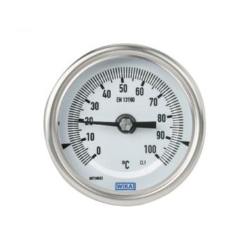
- Nominal sizes 63, 80, 100, 160 mm
- Robust, hermetically sealed case
- External reset for setting the reference temperature
- Dished dial (anti-parallax) for ease of reading
- Adjustable stem and dial version enables optimal process connection
|
Datasheet
|
|
User Manual
|
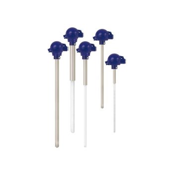
- Application ranges up to max. 1,600 °C / 2,912 °F (DIN EN 50446)
- Thermowell made of heat-resistant steel or ceramic, also with ceramic inner tube
- Support tube of carbon steel
- Gastight process connection
- Coating (optional)
|
Datasheet
|
|
User Manual
|
|
User Manual
|
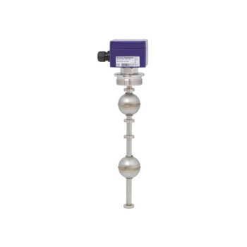
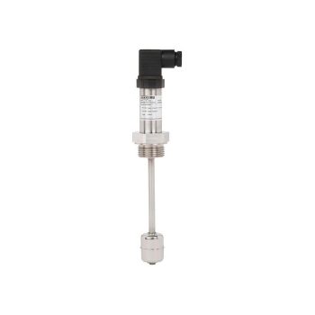
- Freely selectable switch position through fixing the float switch at the required level
- Large range of application due to the simple, proven functional principle
- For harsh operating conditions, long service life
- Operating limits: - Operating temperature: T = -30 ... +150 °C - Operating pressure: P = Vacuum up to 40 bar - Limit density: ρ ≥600 kg/m3
 Datasheet Datasheet |
| User Manual |
- Large range of application due to the simple, proven functional principle
- For harsh operating conditions, long service life
- Operating limits: - Operating temperature: T = -50 ... +350 °C - Operating pressure: P = Vacuum up to 40 bar - Limit density: ρ ≥ 300 kg/m3
- Wide variety of different electrical connections, process connections and materials
- Explosion-protected versions
| Datasheet |
| Datasheet |
| User Manual |
| User Manual |
| User Manual |
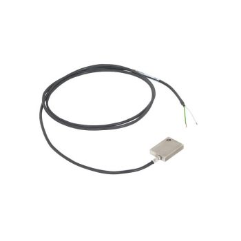
- Einsatz bei Temperaturen bis +170 °C [+338 °F]
- Einbaulage beliebig
- Genauigkeit ±2 mm
- Auswahl elektrischer Anschlüsse: PUR-, PVC-Kabel, Rundstecker M12 x 1 oder Winkelstecker EN 175301-803 A
|
Datenblatt
|
|
Bedienungsanleitung
|
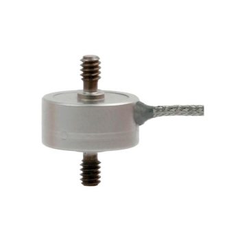
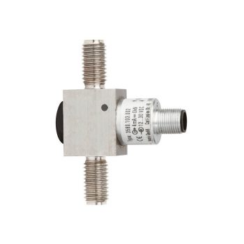
WIKA Model F2221 Miniature tension/compression force transducer For small measuring ranges from 10 N
- Measuring ranges 0 … 10 N up to 0 ... 50 kN
- Standard calibration: tension / compression (positive in tension)
- Ease of assembly
- Small geometries
- Stainless steel version
| Datasheet |
| User Manual |
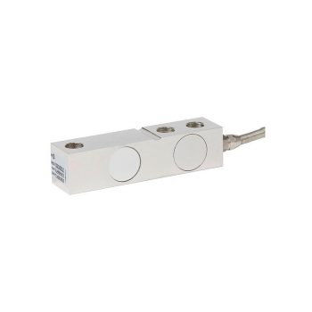
- Measuring ranges 0 … 500 kg up to 0 ... 10.000 kg
- Steel/stainless steel
- High long-term stability
- High side load tolerance
| Datasheet |
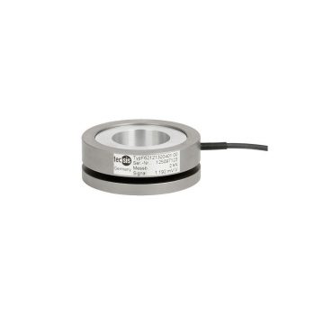
- Measuring ranges 0 ... 1 kN up to 0 ... 1,000 kN
- For compression force measurements
- Simple force introduction, easy installation
- Protection class IP67
- Relative linearity error 0.3 % Fnom (0.1 % Fnom optional)
| Datasheet |

- Highest accuracy and energy efficiency
- No upstream and downstream pipes required
- Wide range of applications
| Datasheet |

- Suitable for liquid, gas and steam flow measurement
- Accuracy ≤ ±0.5 % of actual flow rate
- Repeatability of measurement 0.1 %
- Lowest pressure loss in the family of primary flow elements
- Calibration may be performed if required
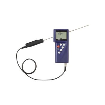
| Datasheet |
| User Manual |
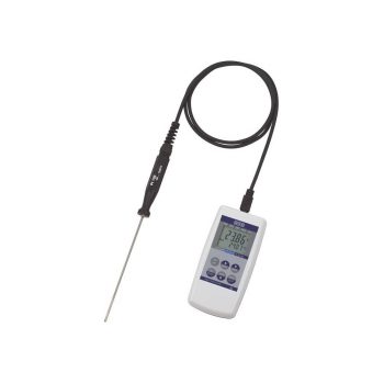
- Pt100 probes for -50 ... +250 °C [-58 ... +482 °F]
- Accuracy: < 0.2 K (complete measuring chain)
- Integrated data logger
- GSoft data logger evaluation software available
- Incl. calibration certificate
| Datasheet |
| User Manual |
- Manual pressure generation of -0.85 … +25 bar [12.3 ... +360 psi]
- Accuracy: 0.025 % FS (incl. calibration certificate)
- Generation/measurement of 0 ... 24 mA and voltage supply DC 24 V
- Data logger with high measuring rate and large memory
- Intrinsically safe version
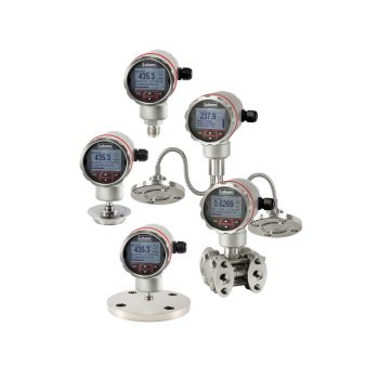
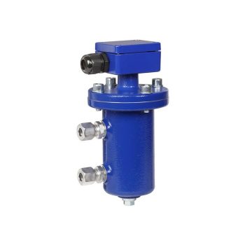
The level transmitter PASCAL Ci4 LEVEL is suitable for the
measurement of level, tank capacity and pressure in
atmospheric and pressurised vessels. The transmitter is
suitable for pressure measurement of aggressive, corrosive,
viscous, high-temperature or solidifying media
![]()
|
Datasheet
|
Coking Plant
In the coking process, coal is converted into coke by heating a carefully prepared coal blend in an oxygen-free environment to temperatures between 1,000 and 1,300 °C. This process typically takes between 16 and 30 hours. The resulting coke serves as a crucial reducing agent in the blast furnace process and significantly contributes to the efficiency and quality of the produced steel.
The composition of the coke, a key factor for its quality, is determined by the selection and blending of different coal types. The challenge lies in achieving a homogeneous mixture that ensures consistent properties for the high-temperature process.
To ensure the ideal conditions for coke production, modern coking plants precisely monitor the pressure and temperature in the coke ovens. This individual monitoring of each oven enables optimized control of the coking process, ensuring consistent coke quality.
For the precise dosing of the coal blend, highly accurate load cells are used. They ensure that the various coal types are mixed exactly according to the recipe to achieve the desired coke quality. These load cells are part of a comprehensive system of measurement and control technology that ensures the smooth handling and processing of large quantities of raw materials.
In addition to process monitoring and control, emission measurements play an important role in coking plants. Environmental regulations require continuous monitoring of pollutant emissions, such as sulfur dioxide and nitrogen oxides, which can be released during the coking process. Modern measurement technology, including gas analyzers and particle counters, is used to ensure compliance with these environmental regulations and protect air quality.
Our tailored measuring instruments for specific requirements are crucial for enhancing efficiency, quality control, and environmental compatibility in coking operations. Through the combination of precise monitoring, advanced analysis techniques, and continuous process improvement, they enable sustainable and cost-effective production of high-quality coke.
- Application ranges up to max. 1,600 °C / 2,912 °F (DIN EN 50446)
- Thermowell made of heat-resistant steel or ceramic, also with ceramic inner tube
- Support tube of carbon steel
- Gastight process connection
- Coating (optional)
|
Datasheet
|
|
User Manual
|
|
User Manual
|
- Measuring ranges 0 ... 1 kN up to 0 ... 1,000 kN
- For compression force measurements
- Simple force introduction, easy installation
- Protection class IP67
- Relative linearity error 0.3 % Fnom (0.1 % Fnom optional)
| Datasheet |
- Pt100 probes for -50 ... +250 °C [-58 ... +482 °F]
- Accuracy: < 0.2 K (complete measuring chain)
- Integrated data logger
- GSoft data logger evaluation software available
- Incl. calibration certificate
| Datasheet |
| User Manual |
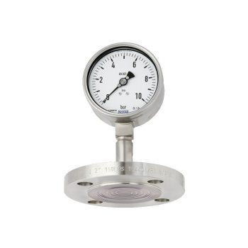
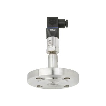
- Flange with a flush welded diaphragm
- Robust, all welded design
- Universal application
| Datasheet |
| User Manual |
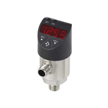
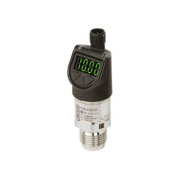
- Easily readable, robust digital display
- Intuitive and fast setup
- Easy and flexible mounting configurations
- Flexibly configurable and scalable output signals
| Datasheet |
| User Manual |
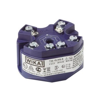
- TÜV zertifizierte SIL-Version für Schutzeinrichtungen entwickelt nach IEC 61508 (Option)
- Einsatz in Sicherheitsanwendungen bis SIL 2 (einzelnes Gerät) und SIL 3 (redundante Verschaltung)
- Konfigurierbar mit nahezu jedem offenen Soft- und Hardwaretool
- Universell für den Anschluss von 1 oder 2 Sensoren - Widerstandsthermometer, Widerstandssensor - Thermoelement, mV-Sensor - Potentiometer
- Signalisierung gemäß NAMUR NE43, Sensorbruchüberwachung gemäß NE89, EMV gemäß NE21

| Datenblatt |
| Bedienungsanleitung |
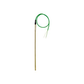
- Sensor ranges -40 ... +1,200 °C (-40 ... +2,192 °F)
- Easily exchanged, no thermowell necessary
- For screw-fitting, welding or using a tightening strap
- Cable from PVC, silicone, PTFE or glass fibre
- Explosion-protected versions
![]()
|
Datasheet
|
|
User Manual
|
|
User Manual
|
|
User Manual
|
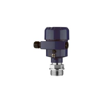
- Process- and system-specific solutions possible
- Operating limits: - Operating temperature: T = -80 ... +200 °C - Operating pressure: P = Vacuum up to 80 bar - Limit density: ρ ≥400 kg/m3
- Wide variety of different electrical connections, process connections and materials
- Optionally with programmable and configurable head-mounted transmitter for 4 ... 20 mA field signals, HART®, PROFIBUS® PA and FOUNDATION™ Fieldbus
- Explosion-protected versions (option)

| Datasheet |
| Datasheet |
| User Manual |
| User Manual |
| User Manual |
- Process- and procedure-specific solutions possible
- Operating limits: - Operating temperature: T = -80 ... +200 °C [-112 ... +392 °F] - Operating pressure: P = vacuum to 80 bar [1,160.3 psi] - Limit density: ρ ≥ 400 kg/m3 [25.0 lbs/ft³]
- Wide variety of different electrical connections, process connections and materials
- 4 ... 20 mA output signal with additional Bluetooth® interface for wireless configuration and level monitoring
| Datasheet |
| User Manual |
| User Manual |
- Process- and procedure-specific solutions possible
- Operating limits: - Operating temperature: T = -80 ... +200 °C [-112 ... +392 °F] - Operating pressure: P = Vacuum to 25 bar [362,6 psi] - Limit density: ρ ≥400 kg/m3 [25,0 lbs/ft3]
- Wide variety of different electrical connections, process connections and materials
- Optionally with programmable and configurable head-mounted transmitter for 4 ... 20 mA field signals, HART®, PROFIBUS® PA and FOUNDATION™ Fieldbus
- Explosion-protected versions (option)
| Datasheet |
| User Manual |
| User Manual |
- IIoT-capable measuring instrument in combination with WIKA radio unit, model NETRIS®3
- Process- and procedure-specific solutions possible
- Operating limits:
- Process temperature:T = -80 ... +200 °C [-112 ... +842 °F]
- Operating pressure: P = vacuum to 80 bar [1,160 psi]
- Limit density: ρ ≥ 400 kg/m3
- Wide variety of different process connections and materials
- Intrinsically safe version Ex i
| Datasheet |
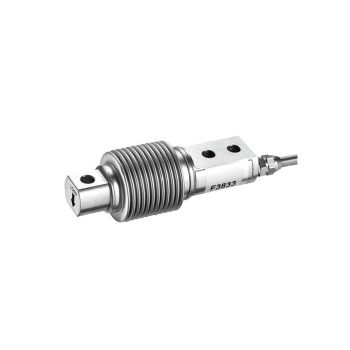
- Measuring ranges 0 … 5 kg up to 0 ... 500 kg
- Completely welded bellows
- Protection class IP68
| Datasheet |
Model CPH6300-S1 (1-channel version) Model CPH6300-S2 (2-channel version)
|
Datasheet
|
|
User Manual
|
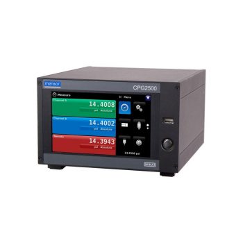
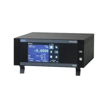
- Pressure ranges: from 0 ... 25 mbar up to 0 ... 2,890 bar [0 ... 0.36 up to 0 ... 42,000 psi]
- Accuracy down to 0.008 % of IS (IntelliScale)
- External pressure ranges from 25 mbar ... 1,000 bar [0.36 ... 15,015 psi]
- Precision 0.004 % FS
- Removable/interchangeable sensors
|
Datasheet
|
|
User Manual
|
Pellet Plant
Pellets are compact, spherical particles made of iron ore that play a key role in steel production. They are formed by the agglomeration of iron ore powder, a byproduct of ore processing. The pelletizing process involves mixing the fine iron ore powder with binders and water, followed by heat treatment, which transforms the initially soft pellets into solid, robust spheres. This shaping is achieved by rolling or kneading the mixture to attain the desired pellet size before subjecting the pellets to a sintering or firing process in a special furnace or on a traveling grate. This thermal treatment leads to the sintering of the particles, imparting the pellets with their final strength and structural integrity.
Additionally, it should be noted that the use of pellets in steel production offers various advantages, including a more uniform chemical composition and higher porosity compared to conventional bulk materials. This enhances the efficiency of iron reduction in the blast furnace, resulting in increased energy efficiency and reduced CO2 emissions. Moreover, pelletization enables the utilization of iron ore fines, which are otherwise considered waste products, thus contributing to a more resource-efficient steel production.
Measurement and testing technology play a crucial role in this process to ensure the quality of pellets. Specialized analytical instruments measure factors such as size, strength, and moisture content of the pellets to ensure compliance with strict industry standards. Furthermore, modern control and regulation systems help optimize the pelletizing process and ensure consistently high product quality.
- Application ranges up to max. 1,600 °C / 2,912 °F (DIN EN 50446)
- Thermowell made of heat-resistant steel or ceramic, also with ceramic inner tube
- Support tube of carbon steel
- Gastight process connection
- Coating (optional)
|
Datasheet
|
|
User Manual
|
|
User Manual
|
- Multi-functional display
- Simple menu navigation
- Conductive plastic case
- Large LC display, rotatable
- Approvals for hazardous areas
| Datasheet |
| User Manual |
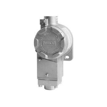
- No power supply needed for switching of electrical loads
- Robust switch enclosure from aluminium alloy or stainless steel with identical dimensions, IP66, NEMA 4X
- Setting ranges from 0.2 ... 1.2 to 200 ... 1,000 bar, vacuum ranges
- Repeatability of the set point ≤ 1% of span
- 1 set point, SPDT or DPDT, high switching power up to AC 250 V, 15 A
| Datasheet |
| User Manual |
- Flange with a flush welded diaphragm
- Robust, all welded design
- Universal application
| Datasheet |
| User Manual |
- Sensor ranges from -40 ... +1,200 °C (-40 ... 2,192 °F)
- For insertion, screw-in with optional process connection
- Cable from PVC, silicone, PTFE or glass fibre
- High mechanical strength
- Explosion-protected versions
| Datasheet |
| User Manual |
| User Manual |
| User Manual |
![]()
|
Datasheet
|
|
User Manual
|
|
User Manual
|
|
User Manual
|
|
User Manual
|
- Process- and procedure-specific production
- Operating limits: - Operating temperature: T = -196 ... +450 °C - Operating pressure: P = Vacuum up to 400 bar
- Wide variety of different process connections and materials
- Mounting of level sensors and guided wave radars possible as an option
| Datasheet |
| User Manual |
- Suitable for measurements in contaminated and aggressive media
- An optimised discharge behaviour and a large pressure port prevent the instrument from clogging and ensure a
minimum maintenance effort - Can be used in explosion-protected areas
- Developed for wireless applications
|
Datasheet
|
|
User Manual
|
|
User Manual
|
- Einsatz bei Temperaturen bis +170 °C [+338 °F]
- Einbaulage beliebig
- Genauigkeit ±2 mm
- Auswahl elektrischer Anschlüsse: PUR-, PVC-Kabel, Rundstecker M12 x 1 oder Winkelstecker EN 175301-803 A
|
Datenblatt
|
|
Bedienungsanleitung
|
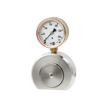
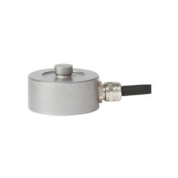
- Measuring ranges 0 ... 1.2 kN to 0 ... 500 kN
- Flattened case for stable measurement
- Relative linearity error ±1.0 ... 1.6 % Fnom with analogue pressure gauge, ±0.5 % Fnom with digital pressure gauge or pressure sensor1)
- Operates without supply voltage
- 5-year leak-tightness warranty2)
| Datasheet |
| User Manual |

- Measuring ranges 0 … 1 t up to 0 ...4 0 t
- Integrated amplifier, output 4 … 20 mA, 2-wire
- Simple mounting (without opening rope), suitable for retrofits
- Material alloyed steel
- Protection class IP66
| Datasheet |
| User Manual |
- Highest accuracy and energy efficiency
- No upstream and downstream pipes required
- Wide range of applications
| Datasheet |
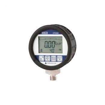
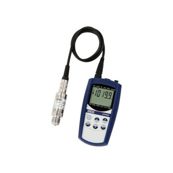
- Measuring ranges from -1 … +16 bar to 0 … 1,000 bar (-14.5 ... 230 psi to 0 ... 14,500 psi)
- Accuracy: 0.25 % (incl. calibration certificate)
- Robust case with protective rubber cap
- Simple operation using four buttons
- Complete service cases incl. pressure generation available
| Datasheet |
| User Manual |
Blast Furnace
In the blast furnace process, the central method for producing pig iron, sinter, pellets, as well as ore, coke, and lime are used as the main materials. These substances are tasked with binding the undesirable components of the ore into slag and lowering the melting temperature of iron. Introduced into the furnace from the top, they encounter hot compressed air introduced from below through blast nozzles. Additionally, auxiliary reducing agents or fuels such as coal, heating oil, natural gas, or other energy sources can be injected directly at the bottom of the furnace to support the process.
Precise monitoring of the pressure and temperature conditions of these fuels, as well as the pressure of the blast furnace gas, is crucial to ensure optimal process control. These measurements not only provide important information for efficient fuel utilization and energy management but are also crucial for the safety of the entire process. Uncontrolled operation can lead to inefficient fuel consumption, increased emissions, and even dangerous operating conditions.
In addition, measuring oxygen concentrations and the composition of blast furnace gas plays an important role. Modern sensors and analysis systems enable the optimization of the combustion process and minimize the emission of pollutants. Continuous monitoring and adjustment of process parameters contribute to increased production efficiency and the quality of the pig iron produced.
Furthermore, advanced monitoring systems enable the early detection of anomalies and deviations in the process flow. This allows for a rapid response to potential problems and helps minimize downtime and extend the life of the equipment. In the modern iron and steel industry, reliable measurement and testing technology, as well as data-based process control, are indispensable for the economical and environmentally friendly operation of blast furnaces.
- Application ranges up to max. 1,600 °C / 2,912 °F (DIN EN 50446)
- Thermowell made of heat-resistant steel or ceramic, also with ceramic inner tube
- Support tube of carbon steel
- Gastight process connection
- Coating (optional)
|
Datasheet
|
|
User Manual
|
|
User Manual
|
- Flange with a flush welded diaphragm
- Robust, all welded design
- Universal application
| Datasheet |
| User Manual |
- Sensor ranges from -40 ... +1,200 °C (-40 ... 2,192 °F)
- For insertion, screw-in with optional process connection
- Cable from PVC, silicone, PTFE or glass fibre
- High mechanical strength
- Explosion-protected versions
| Datasheet |
| User Manual |
| User Manual |
| User Manual |
- Process- and procedure-specific production
- Operating limits: - Operating temperature: T = -196 ... +450 °C - Operating pressure: P = Vacuum up to 400 bar
- Wide variety of different process connections and materials
- Mounting of level sensors and guided wave radars possible as an option
| Datasheet |
| User Manual |
- Suitable for measurements in contaminated and aggressive media
- An optimised discharge behaviour and a large pressure port prevent the instrument from clogging and ensure a
minimum maintenance effort - Can be used in explosion-protected areas
- Developed for wireless applications
|
Datasheet
|
|
User Manual
|
|
User Manual
|
- Measuring ranges 0 … 1 t up to 0 ...4 0 t
- Integrated amplifier, output 4 … 20 mA, 2-wire
- Simple mounting (without opening rope), suitable for retrofits
- Material alloyed steel
- Protection class IP66
| Datasheet |
| User Manual |
- Highest accuracy and energy efficiency
- No upstream and downstream pipes required
- Wide range of applications
| Datasheet |
Process engineering | Chemical industry | Petrochemical industry
![]()
|
Datasheet
|
|
User Manual
|
|
User Manual
|
|
User Manual
|
- Switch differential adjustable within a wide range of up to 60 % of the setting range to realise flexible on/off controls
- Robust aluminium case
- Switch point repeatability of ≤ 0.5 % for reliable switching
- High-quality micro switches with long service life
- Up to 2 possible positions for electrical connection
| Datasheet |
| User Manual |
- Sensor ranges from -196 ... +600 °C [-320 ... +1,112 °F]
- With integrated fabricated protection tube
- Spring-loaded measuring insert (replaceable)
- Explosion-protected versions are available for many approval types (see data sheet page 2)
![]()
|
Datasheet
|
|
Bedienungsanleitung
|
|
Bedienungsanleitung
|
|
Bedienungsanleitung
|
|
Bedienungsanleitung
|
|
Bedienungsanleitung
|
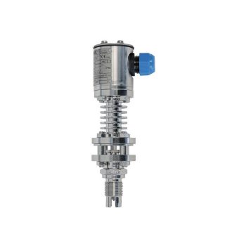
- Temperature ranges from -269 … +400 °C
- Versions for pressure ranges from vacuum to 500 bar
- Special versions: High pressure, interface measurement
- Signal processing is made using a separate model OSA-S switching amplifier
| Datasheet |
| Datasheet |
| User Manual |
- Measuring ranges 0 … 500 kg up to 0 ... 10.000 kg
- Steel/stainless steel
- High long-term stability
- High side load tolerance
| Datasheet |
- Measuring ranges 0 ... 1 kN up to 0 ... 1,000 kN
- For compression force measurements
- Simple force introduction, easy installation
- Protection class IP67
- Relative linearity error 0.3 % Fnom (0.1 % Fnom optional)
| Datasheet |
- Suitable for liquid, gas and steam flow measurement
- Accuracy ≤ ±0.5 % of actual flow rate
- Repeatability of measurement 0.1 %
- Lowest pressure loss in the family of primary flow elements
- Calibration may be performed if required
| Datasheet |
| User Manual |
- Manual pressure generation of -0.85 … +25 bar [12.3 ... +360 psi]
- Accuracy: 0.025 % FS (incl. calibration certificate)
- Generation/measurement of 0 ... 24 mA and voltage supply DC 24 V
- Data logger with high measuring rate and large memory
- Intrinsically safe version
Direct Reduction Plant
Direct reduction of iron (DRI – Direct Reduced Iron) offers an advanced alternative to traditional iron production in blast furnaces. This process has been established worldwide and is operated either with natural gas or coal. The DRI process is characterized by its high energy efficiency. Additionally, additional energy savings can be achieved by immediately introducing the directly reduced, still hot iron into the Electric Arc Furnace (EAF) for further processing.
This approach utilizes the heat released in the direct reduction process for the smelting process in the EAF, reducing the need for external energy input and thus significantly reducing operating costs. Furthermore, the direct reduction process enables a more environmentally friendly production as it causes lower CO2 emissions compared to conventional methods.
State-of-the-art control and measurement technology play a key role in optimizing the direct reduction process and subsequent smelting operations in the EAF. Precise temperature measurement, gas flow control, and real-time monitoring of material quality ensure efficient and continuous production of high-quality iron. Advances in automation and data acquisition enable even more precise process control, increasing productivity and enhancing operational safety.
By combining direct reduction and electric arc furnace, iron and steel producers can not only significantly reduce their energy costs but also respond more flexibly to market demand by quickly and efficiently switching to different types of iron. This makes direct reduction an attractive option for modern iron and steel production.
- Measuring ranges 0 ... 1 kN up to 0 ... 1,000 kN
- For compression force measurements
- Simple force introduction, easy installation
- Protection class IP67
- Relative linearity error 0.3 % Fnom (0.1 % Fnom optional)
| Datasheet |
- Suitable for liquid, gas and steam flow measurement
- Accuracy ≤ ±0.5 % of actual flow rate
- Repeatability of measurement 0.1 %
- Lowest pressure loss in the family of primary flow elements
- Calibration may be performed if required
| Datasheet |
| User Manual |
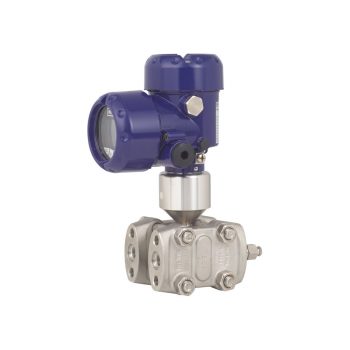
- Differential pressure measuring ranges from 0 … 16 mbar
- High working pressure (static pressure) and high overload safety up to 40 bar
- Also available with liquid-filled case for high dynamic pressure loads or vibrations
- Instruments with inductive contacts for use in hazardous areas
- Instruments with switch contact for PLC applications
|
Datasheet |
| User Manual |
| User Manual |
- No power supply needed for switching of electrical loads
- Robust switch enclosure from aluminium alloy or stainless steel with identical dimensions, IP66, NEMA 4X
- Setting ranges from 0.2 ... 1.2 to 200 ... 1,000 bar, vacuum ranges
- Repeatability of the set point ≤ 1% of span
- 1 set point, SPDT or DPDT, high switching power up to AC 250 V, 15 A
| Datasheet |
| User Manual |
- For many variants of temperature transmitters including field transmitter
- For mounting in all standard thermowell designs
- Spring-loaded measuring insert (replaceable)
- Explosion-protected versions (option)
![]()
|
Datasheet
|
|
User Manual
|
|
User Manual
|
|
User Manual
|
|
User Manual
|
- 3 times longer service life in comparison to purely ceramic protection tubes due to the monocrystalline structure of the sapphire sensor
- High process safety with processes up to 1,700 °C [3,092 °F] and 65 bar [943 psi]
- Reduction of unplanned downtime
- Increased safety through double sealing system against escape of toxic media
- Cost savings through the elimination of a purge system and the repairability of the sensor
| Datasheet |
| User Manual |
| User Manual |
- Large range of application due to the simple, proven functional principle
- For harsh operating conditions, long service life
- Operating limits: - Operating temperature: T = -50 ... +350 °C - Operating pressure: P = Vacuum up to 40 bar - Limit density: ρ ≥ 300 kg/m3
- Wide variety of different electrical connections, process connections and materials
- Explosion-protected versions
| Datasheet |
| Datasheet |
| User Manual |
| User Manual |
| User Manual |
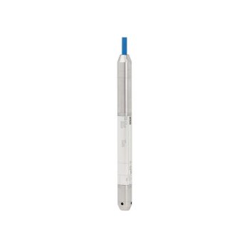
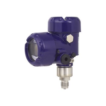
- Slender design
- Scaleable measuring range (option)
- Resistant against harshest environmental conditions
- Reliable and secure by double-sealed design
- Titanium case for especially high resistance (option)
|
Datasheet
|
|
Datasheet
|
|
User Manual
|
- Measuring ranges 0 ... 1 kN to 0 ... 500 kN [0 ... 224.8 lbf to 0 ... 112,404 lbf]
- Stainless steel version (corrosion-resistant)
- Integrated amplifier
- High long-term stability, high shock and vibration resistance
- Good reproducibility, easy installation
| Datasheet |
| User Manual |
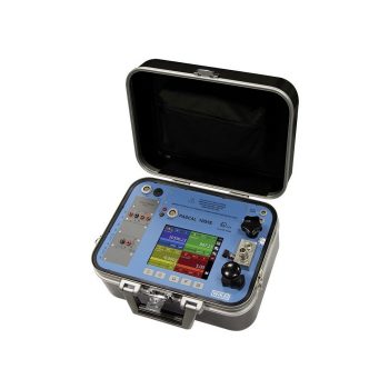
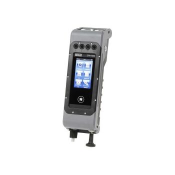
Due to its versatility the hand-held multifunction calibrator
Pascal series is ideally suited for on-field testing and
calibration of industrial measuring instruments.
Datasheet
Oxygen Steel Converter
In the steelworks, the liquid pig iron originating from the blast furnace is used for the production of raw steel. This process takes place in converters, where the carbon contained in the pig iron is oxidized by blowing in pure oxygen. A central trend in steel production is the increase in steel qualities, coupled with enhanced flexibility of metallurgical processes. Furthermore, the continuous optimization of logistic processes in the steelworks is a continuous challenge.
The elimination of interfering elements such as carbon, silicon, sulfur, and phosphorus is a crucial step in steel production in the Basic Oxygen Furnace (BOF). The blowing of oxygen into the oxygen steel converter effectively reduces these elements. During this process, temperatures in the converter reach values of up to 1,700 °C, necessitating precise control and monitoring of process conditions.
Modern steel production processes also integrate advanced technologies for energy efficiency and reducing environmental impacts. The use of secondary energy streams, the recycling of process gases for energy generation, and the use of environmental technologies for exhaust gas cleaning are examples of sustainable practices in the steel industry.
Measurement and testing technology play a crucial role in ensuring the quality and efficiency of steel production. From precise temperature measurement to gas composition analysis and monitoring of material composition, advanced measuring instruments and systems enable precise process control and maximize product quality.
Innovative methods of material testing, such as non-destructive testing, also contribute to ensuring the integrity and reliability of manufactured steel products. The continuous advancement of measurement technology and metallurgical processes enables the steel industry to meet the increasing demands for quality, sustainability, and flexibility.
- Measuring ranges 0 ... 1 kN to 0 ... 500 kN [0 ... 224.8 lbf to 0 ... 112,404 lbf]
- Stainless steel version (corrosion-resistant)
- Integrated amplifier
- High long-term stability, high shock and vibration resistance
- Good reproducibility, easy installation
| Datasheet |
| User Manual |
- Easily readable, robust digital display
- Intuitive and fast setup
- Easy and flexible mounting configurations
- Flexibly configurable and scalable output signals
| Datasheet |
| User Manual |
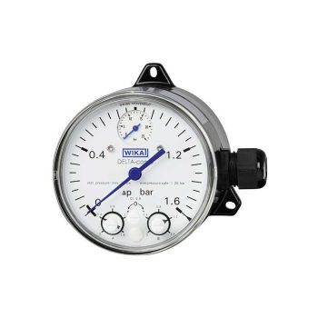
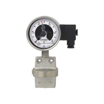
- With one or two adjustable microswitches
- Shatterproof window and robust aluminium or stainless steel measuring chamber for increased requirements
- Optionally with approvals for hazardous areas
- High ingress protection, IP65, for outdoor use and processes with high condensation
- Low measuring range from 0 ... 250 mbar
| Datasheet |
| User Manual |
![]()
|
Datasheet
|
|
User Manual
|
- Sensor ranges -40 ... +1,200 °C (-40 ... +2,192 °F)
- Easily exchanged, no thermowell necessary
- For screw-fitting, welding or using a tightening strap
- Cable from PVC, silicone, PTFE or glass fibre
- Explosion-protected versions
![]()
|
Datasheet
|
|
User Manual
|
|
User Manual
|
|
User Manual
|
- Application ranges from 0 ... 1,200 °C (32 ... 2,192 °F)
- Made of mineral-insulated sheathed cable
- Explosion-protected versions
![]()
|
Datasheet
|
|
User Manual
|
|
User Manual
|
- Media compatibility: Oil, water, diesel, refrigerants and other liquids
- Level: Up to 3 switching outputs, freely definable as normally open, normally closed or change-over contact
- Temperature: 1 bimetal temperature switch or Pt100/Pt1000, accuracy: Class B
- Potential-free switching reed contacts
| Datasheet |
| User Manual |
- Freely selectable switch position through fixing the float switch at the required level
- Large range of application due to the simple, proven functional principle
- For harsh operating conditions, long service life
- Operating limits: - Operating temperature: T = -30 ... +150 °C - Operating pressure: P = Vacuum up to 40 bar - Limit density: ρ ≥600 kg/m3
| Datasheet |
| User Manual |
- Measuring ranges strains from 0 ... 200 με up to max. 0 ... 1,000 με
- Good long-term stability, high shock and vibration resistance, good reproducibility
- As retrofitting, easy to install
- For use in extreme outdoor applications (IP67)
- Relative linearity error < 2 % Fnom
| Datasheet |
| User Manual |
- Measuring ranges 0 ... 5 kN to 0 ... 200 kN [0 ... 1,124 lbf to 0... 44,962 lbf]
- Stainless steel version (corrosion-resistant)
- Integrated amplifier
- High long-term stability, high shock and vibration resistance
- Good reproducibility, simple installation
| Datasheet |
| User Manual |
- Pressure ranges: -1 ... 210 bar (-15 ... 3,045 psi)
- Control speed 10 s
- Control stability < 0.005 % FS
- Accuracy to 0.02 % IS (IntelliScale)
- Precision 0.008 % FS
|
Datasheet
|
|
User Manual
|
- High accuracy of 0.03 K with Pt100
- One- and two-channel versions
- Connection possibilities for various probe types
- Intrinsically safe version Ex ib IIB T4 Gb
![]()
| Datasheet |
| User Manual |
| User Manual |
Electric Arc Furnace
Steels primarily made from recycled scrap utilize the Electric Arc Furnace (EAF) as a key component in the production process. Once the furnace is charged with scrap, the melting process begins by igniting the electric arc. To expedite the melting process and minimize electrical energy consumption, oxygen as well as fuel gas mixture is introduced directly into the melt through specialized lances, burner systems, and injectors.
Precise monitoring and control of fuel pressure, temperature, and flow rates are essential to ensure efficient and optimized operating conditions. These measurement data provide the basis for standardized consumption and operational statistics, which are indispensable for effective process monitoring and control.
In addition to monitoring the mentioned parameters, analyzing the gas composition in the furnace chamber is important to achieve optimal combustion and energy efficiency. Furthermore, continuous monitoring of the furnace atmosphere and control of the exhaust gas cleaning systems play a crucial role in complying with environmental regulations and minimizing pollutant emissions. Innovative sensor technologies and automation systems contribute to increasing process efficiency and ensuring product quality while conserving resources and reducing environmental impact.
- Measuring ranges 0 ... 1 kN to 0 ... 500 kN [0 ... 224.8 lbf to 0 ... 112,404 lbf]
- Stainless steel version (corrosion-resistant)
- Integrated amplifier
- High long-term stability, high shock and vibration resistance
- Good reproducibility, easy installation
| Datasheet |
| User Manual |
- With one or two adjustable microswitches
- Shatterproof window and robust aluminium or stainless steel measuring chamber for increased requirements
- Optionally with approvals for hazardous areas
- High ingress protection, IP65, for outdoor use and processes with high condensation
- Low measuring range from 0 ... 250 mbar
| Datasheet |
| User Manual |
- Freely selectable switch position through fixing the float switch at the required level
- Large range of application due to the simple, proven functional principle
- For harsh operating conditions, long service life
- Operating limits: - Operating temperature: T = -30 ... +150 °C - Operating pressure: P = Vacuum up to 40 bar - Limit density: ρ ≥600 kg/m3
| Datasheet |
| User Manual |
- Measuring ranges strains from 0 ... 200 με up to max. 0 ... 1,000 με
- Good long-term stability, high shock and vibration resistance, good reproducibility
- As retrofitting, easy to install
- For use in extreme outdoor applications (IP67)
- Relative linearity error < 2 % Fnom
| Datasheet |
| User Manual |
- Measuring ranges 0 ... 5 kN to 0 ... 200 kN [0 ... 1,124 lbf to 0... 44,962 lbf]
- Stainless steel version (corrosion-resistant)
- Integrated amplifier
- High long-term stability, high shock and vibration resistance
- Good reproducibility, simple installation
| Datasheet |
| User Manual |
Process engineering | Chemical industry | Petrochemical industry
![]()
|
Datasheet
|
|
User Manual
|
|
User Manual
|
|
User Manual
|
- Sensor ranges from -40 ... +1,200 °C (-40 ... 2,192 °F)
- For insertion, screw-in with optional process connection
- Cable from PVC, silicone, PTFE or glass fibre
- High mechanical strength
- Explosion-protected versions
| Datasheet |
| User Manual |
| User Manual |
| User Manual |
- Sensor ranges from -196 ... +600 °C (-320 ... +1.112 °F)
- For mounting in all standard thermowell designs
- Spring-loaded measuring insert (replaceable)
- Pt100 or Pt1000 sensors
- Explosion-protected versions
| Datasheet |
| User Manual |
| User Manual |
| User Manual |
| User Manual |
| User Manual |
- Media compatibility: Oil, water, diesel, refrigerants and other liquids
- Permissible medium temperature range: -30 ... +120 °C [-22 ... +248 °F]
- Output signal: Resistance in a 3-wire potentiometer circuit, current output 4 ... 20 mA
- Measuring principle: Reed-chain technology
- Accuracy, resolution: 24 mm [0.9 in], 12 mm [0.5 in], 10 mm [0.4 in], 6 mm [0.2 in] oder 3 mm [0.1 in]
| Datasheet |
| User Manual |
- Temperature ranges from -269 … +400 °C
- Versions for pressure ranges from vacuum to 500 bar
- Special versions: High pressure, interface measurement
- Signal processing is made using a separate model OSA-S switching amplifier
| Datasheet |
| Datasheet |
| User Manual |
The VDMA standard for fluid sensors (24574-1, part 1 - pressure switches) has the aim of simplifying the use of pressure switches by standardising menu navigation and display.
- Easily-readable, robust display
- Intuitive and fast setup
- Easy and flexible mounting configurations
|
Datasheet
|
Pan Furnace
In secondary metallurgy, a crucial step in the steel manufacturing process, the pan furnace is employed to enhance the quality of liquid steel through targeted treatments such as desulfurization, and to precisely tailor it to the specific requirements of customers. Fine-tuning of steel properties is achieved through the addition of alloying elements and precise temperature control to attain the desired mechanical properties and purity levels.
The furnace lid and other critical components of the pan furnace are equipped with high-quality refractory materials and protected by water-cooled systems. This cooling is essential not only for the furnace lid but also for the exhaust duct, electrode arms, and electrical connections to ensure the integrity of the plant and prevent overheating.
Our resistance thermometers and pressure sensors play a key role in maintaining an efficient cooling circuit, known for their robustness and reliability in harsh operating environments. These instruments continuously monitor the water pressure and temperature, crucial for optimal cooling performance and therefore essential for the longevity of refractory linings and cooled components. Thanks to their compact design, pressure sensors can be seamlessly integrated into existing systems with minimal installation effort.
In addition to these measuring instruments, flow meters can be used to accurately measure the speed and quantity of cooling water, allowing further fine-tuning of the cooling process. By utilizing advanced diagnostic tools and intelligent monitoring systems, anomalies in the cooling circuit can be detected and rectified early, minimizing downtime and maximizing production efficiency.
The integration of modern sensor technology into the monitoring of critical process parameters significantly contributes to the optimization of steel production, enabling precise control over cooling and thus the quality of the end product.
- Measuring ranges 0 ... 1 kN to 0 ... 500 kN [0 ... 224.8 lbf to 0 ... 112,404 lbf]
- Stainless steel version (corrosion-resistant)
- Integrated amplifier
- High long-term stability, high shock and vibration resistance
- Good reproducibility, easy installation
| Datasheet |
| User Manual |
- Sensor ranges from -40 ... +1,200 °C (-40 ... 2,192 °F)
- For insertion, screw-in with optional process connection
- Cable from PVC, silicone, PTFE or glass fibre
- High mechanical strength
- Explosion-protected versions
| Datasheet |
| User Manual |
| User Manual |
| User Manual |
- Easily readable, robust digital display
- Intuitive and fast setup
- Easy and flexible mounting configurations
- Flexibly configurable and scalable output signals
| Datasheet |
| User Manual |
- Good/bad indication through parameterisable digital display (red/green)
- Compact size enables easy installation in narrow spaces
- Optimised design makes OEM machine integration easier
- Designed for rough demands of up to 50 g shock and -40 ... +125 °C [-40 ... +257 °F]
| Datasheet |
| User Manual |
- No configuration necessary due to "plug-and-play"
- Signal transmission per NAMUR
- Measuring ranges 0 ... 0.6 bar to 0 ... 1,600 bar
- Easy-to-read analogue display with nominal size 100 or 160
- Safety version S3 per EN 837
| Datasheet |
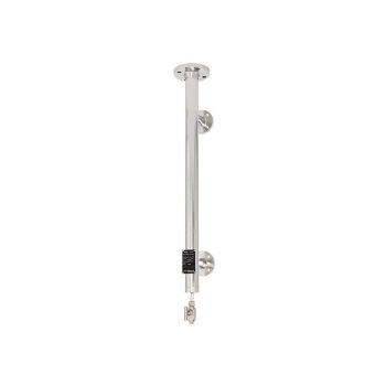
- Sensor ranges up to max. 1,200 °C (2,193 °F)
- Single and dual thermocouple
- Good heat transfer through adjustable spring-loading
- Easy installation and removal, no tools needed
- Explosion-protected versions
![]()
|
Datasheet
|
|
User Manual
|
|
User Manual
|
|
User Manual
|
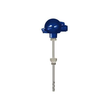
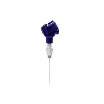
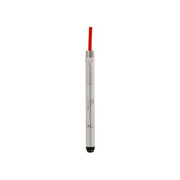
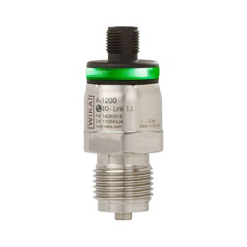
- Sensor ranges from -196 ... +500 °C [-320 ... +932 °F]
- Compact design
- Universal application
- Direct installation into the process
- Explosion-protected versions are available for many approval types (see data sheet page 2)
| Datasheet |
| User Manual |
| User Manual |
| User Manual |
| User Manual |
| User Manual |
- Slender design
- Scaleable measuring range (option)
- Resistant against harshest environmental conditions
- Reliable and secure by double-sealed design
- Titanium case for especially high resistance (option)
|
Datasheet
|
|
Datasheet
|
|
User Manual
|
- Measuring ranges 0 … 500 kg up to 0 ... 10.000 kg
- Steel/stainless steel
- High long-term stability
- High side load tolerance
| Datasheet |
- Measuring ranges 0 ... 2 kN up to 0 ... 100 kN
- For compression force measurements
- Flat dimensions
- Stainless steel measuring body
- Protection class IP65
| Datasheet |
Model CPH6300-S1 (1-channel version) Model CPH6300-S2 (2-channel version)
|
Datasheet
|
|
User Manual
|
Continuous Casting System
In the continuous casting process, molten steel is directed from the ladle into molds through a distributor. The ladle, filled with liquid steel, is positioned in a rotating frame capable of accommodating two ladles simultaneously. Thermal monitoring and pressure measurement techniques are employed for monitoring the casting process and early detection of potential breakthroughs or leaks of liquid steel.
To prevent breakthroughs and monitor steel cooling, it is crucial to capture a detailed temperature profile within the mold. This aids in detecting crack formation, thus ensuring the integrity of the cast strand. Thermocouples are strategically placed on the narrow and wide sides of the mold to provide comprehensive, two-dimensional temperature profiling. In addition to temperature monitoring, measuring the inlet and outlet temperatures of the cooling water and the flow rate of coolant is vital for assessing heat dissipation efficiency.
Furthermore, the use of ultrasonic sensors to monitor the levels of molten steel in the distributor is recommended to ensure uniform distribution of molten steel and prevent overflows. Analyzing the vibration patterns of the mold can also be useful in early detection of mechanical irregularities or instabilities that could compromise the quality of the cast strand.
By employing advanced measurement techniques and precise monitoring methods, process stability and product quality in continuous casting can be significantly enhanced. These measures contribute to optimizing production efficiency and minimizing the risk of equipment downtime and production losses.
- Measuring ranges 0 … 500 kg up to 0 ... 10.000 kg
- Steel/stainless steel
- High long-term stability
- High side load tolerance
| Datasheet |
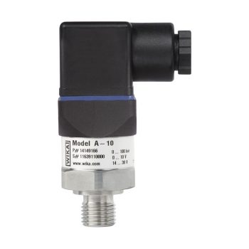
- Measuring ranges from 0 … 0.05 to 0 … 1,000 bar
- Non-linearity 0.25 % or 0.5 %
- Output 4 ... 20 mA, DC 0 ... 10 V, DC 0 ... 5 V and others
- Electrical connection: Angular connector form A and C, circular connector M12 x 1, cable outlet 2 m
- Process connection G ¼ A DIN 3852-E, ¼ NPT and others
|
Datasheet |
| User Manual |
- Up to 4 switch contacts per instrument
- Also available with case filling for high dynamic pressure loads or vibrations
- Instruments with inductive contacts for use in hazardous areas
- Instruments with contacts for PLC applications
- Instruments optionally available in safety version S3 per EN 837
| Datasheet |
| User Manual |
| User Manual |
- Industry 4.0-ready IO-Link sensor improves connectivity and diagnostics
- Designed for rough demands of up to 1,000 g shock and -40 ... +125 °C [-40 ... +257 °F]
- Optimised design makes OEM machine integration easier
- Multicolour 360° LED status display simplifies troubleshooting and localisation
| Datasheet |
| User Manual |
![]()
|
Datasheet
|
|
User Manual
|
![]()
|
Datasheet
|
|
User Manual
|
|
User Manual
|
|
User Manual
|
|
User Manual
|
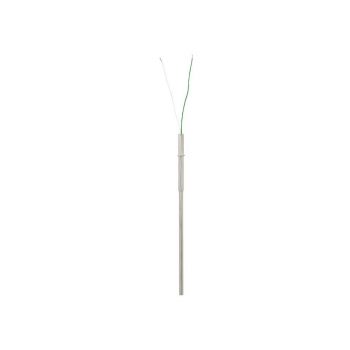
- Sensor ranges from -40 ... +1,200 °C [-40 ... +2,192 °F]
- With integrated fabricated protection tube
- Spring-loaded measuring insert (replaceable)
- Explosion-protected versions are available for many approval types (see data sheet page 2)
![]()
|
Datasheet
|
|
User Manual
|
|
User Manual
|
|
User Manual
|
- Einsatz bei Temperaturen bis +170 °C [+338 °F]
- Einbaulage beliebig
- Genauigkeit ±2 mm
- Auswahl elektrischer Anschlüsse: PUR-, PVC-Kabel, Rundstecker M12 x 1 oder Winkelstecker EN 175301-803 A
|
Datenblatt
|
|
Bedienungsanleitung
|
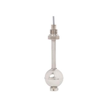
- Media compatibility: Oil, water, diesel, refrigerants and other liquids
- Level: Up to 3 switching outputs, freely definable as normally open, normally closed or change-over contact
- Temperature: 1 bimetal temperature switch or Pt100/Pt1000, accuracy: Class B
- Potential-free switching reed contacts
| Datasheet |
| User Manual |
- Suitable for measurements in contaminated and aggressive media
- An optimised discharge behaviour and a large pressure port prevent the instrument from clogging and ensure a
minimum maintenance effort - Can be used in explosion-protected areas
- Developed for wireless applications
|
Datasheet
|
|
User Manual
|
|
User Manual
|
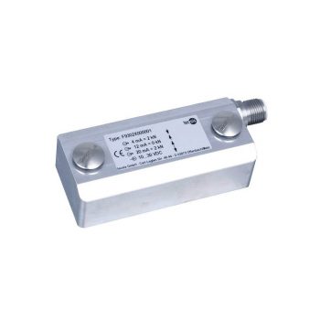
- Measuring ranges strains from 0 ... 200 με up to max. 0 ... 1,000 με
- Good long-term stability, high shock and vibration resistance, good reproducibility
- As retrofitting, easy to install
- For use in extreme outdoor applications (IP67)
- Relative linearity error < 2 % Fnom
| Datasheet |
| User Manual |
- Manual pressure generation of -0.85 … +25 bar [12.3 ... +360 psi]
- Accuracy: 0.025 % FS (incl. calibration certificate)
- Generation/measurement of 0 ... 24 mA and voltage supply DC 24 V
- Data logger with high measuring rate and large memory
- Intrinsically safe version
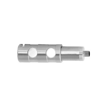
- Pressure ranges: -1 ... 210 bar (-15 ... 3,045 psi)
- Control speed 10 s
- Control stability < 0.005 % FS
- Accuracy to 0.02 % IS (IntelliScale)
- Precision 0.008 % FS
|
Datasheet
|
|
User Manual
|